
When an illustrative telecom site supervisor in Rotterdam cut a duct end square and pushed on a new connector, the visible failure appeared within minutes: the joint did not seat cleanly and the air path would not hold. A review of the job sheet reversed the first assumption. The connector was not automatically a bad product; the selected size did not match the measured duct, and the installation method had not defined the sealing and support conditions. That is the practical problem behind how to choose a microduct connector: selection, sizing, environment and process must agree before the part reaches the trench.
Résumé : Choose a microduct connector from measured duct dimensions, the joint type required, the route environment, the sealing duty and the access needed for maintenance. IEC 60794-5:2020 addresses outdoor microducts, while ISO 9001:2015 addresses a manufacturer’s quality-management system; neither is, by itself, proof that a particular connector is certified for every route. The recommended action is to record the actual duct size and construction, select a documented connector family, and verify seating and sealing at installation before approving the route.
What must match before a connector is selected?
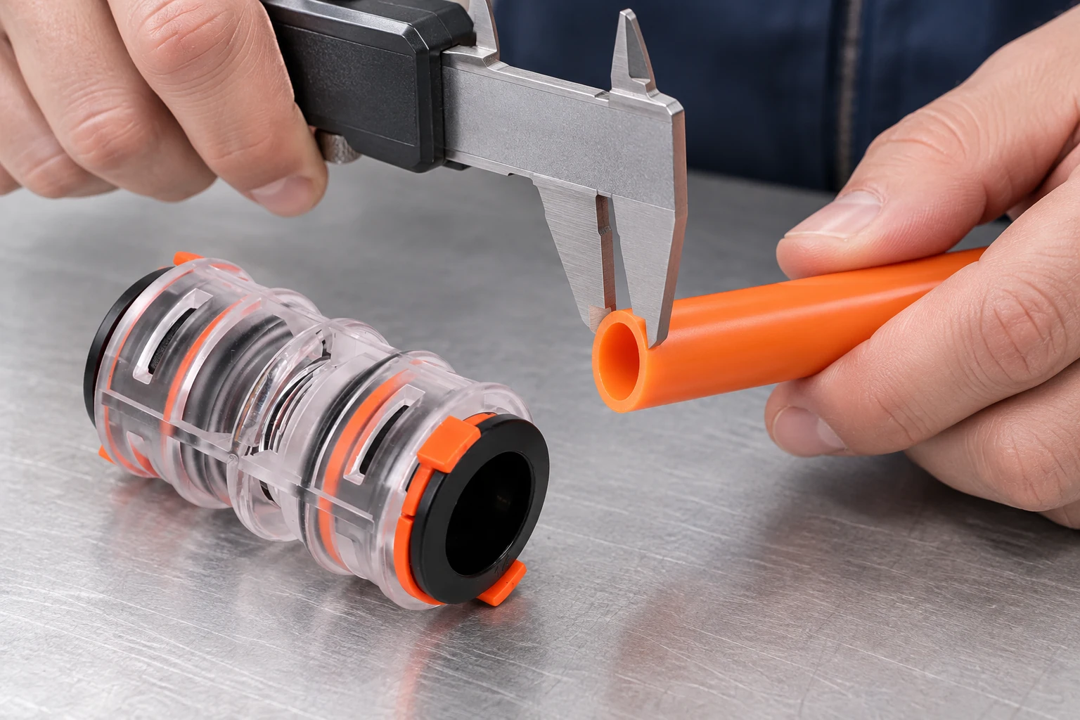
A connector is a dimensional and functional interface, not just a sleeve that joins two tube ends. Start by identifying the microduct material and measuring the actual outside diameter and relevant wall or bore information at the joint location. Compare those observations with the manufacturer’s product data; do not select by a nominal label copied from an old drawing when the installed duct may come from a different batch or format.
Next, define what the joint must do. A straight connector keeps the same duct path; a reducing connector joins different sizes only when that transition is intended by the design. An end plug or termination component has a different duty from a through-connector because it closes and protects an open end. The selection should also state whether the connection is temporary during construction or expected to remain in the route for the service life of the installation.
- Size: Record the measured duct dimensions and compare them with the connector’s specified range.
- Geometry: Confirm whether the route needs a straight joint, a planned reduction, a branch, or an end closure.
- Environment: Identify underground, access-pit, exposed, wet, or direct-buried conditions in the project specification.
- Sealing duty: State whether the connection must retain an air path, exclude moisture, protect a spare duct, or meet another documented requirement.
- Access: Leave enough room to inspect, remake, label or replace the joint without damaging adjacent ducts.
How do connector geometry and route environment change the decision?
The same nominal duct size can require different decisions when the route geometry or environment changes. A straight run may need a compact through-connector, while a transition between duct sizes needs a documented reducing part and a clear direction of assembly. A connector installed in an access pit may be easy to inspect, but a buried joint needs the project team to confirm that the selected components and protection method are appropriate for burial. Appearance is not evidence of direct-burial suitability.
Consider the full HDPE system rather than the joint in isolation. The HDPE microduct guide can help installers frame the relationship between duct construction and fiber installation, but the project specification and current product documentation remain the decision records. If a route contains mixed duct materials, unusual wall thicknesses or a repair section, record that fact and obtain compatibility confirmation before ordering a connector.
| Point de décision | Evidence to record | Selection consequence |
|---|---|---|
| Duct dimensions | Measured outside diameter, bore or wall information, and any variation at the joint | Choose a connector whose documented range matches the installed duct |
| Géométrie des joints | Straight run, planned reduction, branch, repair or termination | Use the connector type designed for that relationship; do not improvise a transition |
| Route environment | Underground, access-pit, exposed, wet or direct-buried condition | Confirm the sealing, protection and installation duty in the project documents |
| Air and moisture duty | Required air path, moisture exclusion or spare-duct protection | Specify the relevant seal and end-protection arrangement |
| Maintenance access | Working space, label position and future inspection or replacement route | Allow the joint to be checked or remade without stressing the duct |
What installation process prevents leaks and misalignment?
Good connector selection can still fail when the duct end is poorly prepared. Cut the duct square with the approved tool, remove debris and burrs, and check that the end is not ovalised or damaged. Align the two ducts before insertion, then push them fully into the connector according to the supplier’s instructions. Do not twist, bend or force the assembly to compensate for a wrong size or an obstructed route.
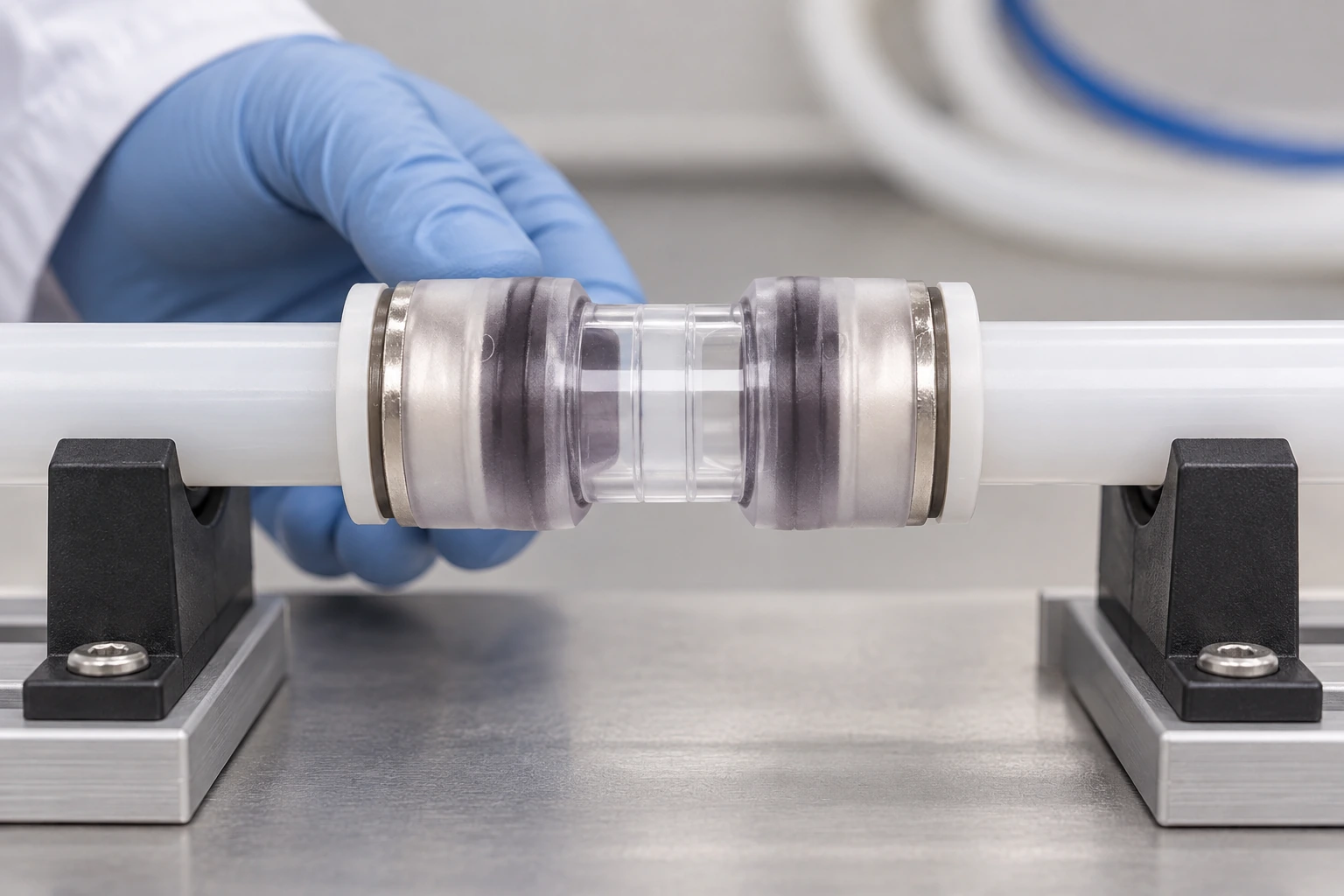
After assembly, inspect the seating and support. A transparent connector can make the insertion position visible, but visual confirmation is only one part of acceptance. The joint must also be protected from side loads, sharp bend transitions and accidental movement during backfill or later cable work. Keep the end clean until the connection is made, and fit the specified plug or cap whenever a duct is left open.
The site’s production procedure article provides manufacturing context, but it should not replace the installation method statement. The field record should identify the duct, connector type, installer, date, location and any corrective action. That record lets a maintenance team distinguish a sizing issue from a later route disturbance.
How can a buyer verify sealing and maintenance access?
The honest answer is that a connector is airtight only when the duct dimensions, clean cuts, seal components and insertion depth all match the specified assembly. A visual check can reveal incomplete seating or a displaced seal, but it does not prove leak-tightness on its own. Use the project’s approved pressure, leak or continuity check where one is required, and record the method and result rather than copying a pass value from an unrelated route.
Maintenance access is part of the same decision. A joint hidden behind a tight bend or unsupported at an access point can be difficult to inspect even if it initially holds air. Leave a clear label and service path, protect the connector from movement, and document any transition that future crews may mistake for a standard straight joint.
| Acceptance item | What the installer checks | What the handover record should show |
|---|---|---|
| Identity and location | Correct duct route, joint position and connector type | Route mark-up, label and component reference |
| End preparation | Square, clean, undamaged cuts and compatible duct ends | Inspection sign-off or installation photograph |
| Seating and support | Full insertion, visible alignment and no avoidable side load | Installer check and any corrective-action note |
| Seal or closure check | Specified seals, plugs or caps installed for the route condition | Component and environmental-duty record |
| Project test | Approved pressure, leak, continuity or other required check | Test method, date, result and responsible person |
| Future access | Label, working space and protection retained after completion | As-built drawing and maintenance note |
Which connector should be used for an air-blown fiber route?
For an air-blown fiber route, select a connector that preserves the intended duct path and sealing condition while presenting a clean, supported bore to the installation equipment. Check the cable-and-duct plan, the connector dimensions, the end preparation method and the access-point arrangement together. The air-blown fiber installation comparison is useful for framing the route decision, but it does not establish a universal connector, pressure or distance limit.
Before blowing, verify continuity and remove or document obstructions. During the operation, stop if the cable behavior, air loss or connector movement differs from the approved method. Afterward, protect the cable end, inspect the joint and retain the optical and route records required by the contract. A connector that looks correct before blowing still needs post-installation acceptance.
Which standards should procurement teams cite?
Standards help define scope and verification; they should not be used as shorthand for unsupported product claims.
- IEC 60794-5:2020: Covers fibre-optic cable systems involving outdoor microducts. Use its scope alongside the project’s duct, connector and installation requirements.
- EN 50411-2-8: Relates to fibre-management systems and protective housings. Confirm that the relevant component and intended use fall within the document’s scope before citing it.
- ISO 9001:2015: Specifies quality-management-system requirements. It is not a product certification, a dimensional guarantee or proof that a connector suits a particular environment.
Commercially, unsupported standards language can mislead a buyer and make acceptance harder. Ask for the current declaration, technical data and test evidence that apply to the exact component and destination market. If the project requires a regulatory or customer-specific approval, state that requirement in procurement rather than assuming a general standard covers it.
What should buyers do before ordering?
- Measure the installed duct and attach the result to the purchase or technical query.
- Define the joint geometry, route environment, sealing duty and expected maintenance access.
- Request the connector drawing, installation instructions and compatibility statement for the selected duct.
- Agree the field inspection and any approved leak, pressure or continuity check before delivery.
- Require the handover records that will identify the joint and support future cable work.
Oulu / ANMASPC presents microduct connectors, duct plugs, HDPE microducts and related pneumatic products for B2B sourcing. Review the current microduct connector range against the project specification, then ask for route-specific documentation before committing to a size or connector type. Product availability, configuration and any certification claim should be confirmed in the current supplier documents.
Frequently asked questions about microduct connector selection
How do I measure a microduct before choosing a connector?
Identify the duct at the actual joint, make a clean inspection cut if permitted, and record the outside diameter plus the relevant bore or wall information. Compare the measured condition with the connector drawing and specified range. If the duct is ovalised, damaged or from a mixed batch, pause and obtain a compatibility decision instead of relying on the label alone.
What is the difference between a straight and reducing microduct connector?
A straight connector joins compatible duct ends on the same intended path and size. A reducing connector is designed for a planned transition between different duct sizes and should be selected from a documented size pairing. It is not a substitute for correcting a measurement error or forcing mismatched ducts together.
Do microduct connectors need to be rated for direct burial?
That depends on the route design and the connector, seal and protection arrangement specified for it. Direct-burial suitability should be confirmed in current product documentation and the project specification; it cannot be inferred from a connector’s appearance or nominal size. Record the environmental duty before ordering.
How do I know whether a connector is airtight?
First verify the duct dimensions, clean square cuts, full insertion and correct seals. Then perform the project-approved pressure, leak or continuity check when required, because a visual seating check alone cannot establish airtightness. Keep the method and result with the joint record.
Can I reuse a push-fit microduct connector?
Reuse should be allowed only when the manufacturer’s instructions and the project method permit it. Inspect the connector, seals and duct ends for damage, contamination or loss of retention, and replace any component outside the documented condition. A connector that has been removed from a stressed or buried joint needs particular scrutiny.
Which connector should I use for an air-blown fiber route?
Use the connector that matches the duct dimensions, route geometry, sealing duty and air-blown installation method documented for the project. Confirm that the joint is fully seated, supported and free of avoidable air leaks before blowing. The cable, duct, connector and equipment should be checked as one system rather than selected independently.
Références
- IEC standards catalogue (search for IEC 60794-5:2020, Fibre optic cables — Part 5: Outdoor microducts).
- EN 50411-2-8, Fibre management systems and protective housings.
- ISO 9001:2015, Quality management systems — Requirements.
Conclusion
Choosing the right microduct connector is a controlled interface decision: measure the installed duct, define the joint geometry, identify the route environment, state the sealing duty and preserve maintenance access. Then follow a documented preparation and seating process, check the joint with the project’s approved method, and retain a route record that another crew can understand. Do not solve a poor fit by forcing the duct, adding unapproved materials or increasing installation pressure. Oulu / ANMASPC can help buyers compare connector, plug and microduct options, but the final choice should be tied to the actual duct and project specification. Review the microduct connector range and contact the supplier for compatibility documents before ordering.


