
When a network supervisor in Manchester, UK, asked a crew to reconnect a 12 mm HDPE microduct before a night fiber-blowing window, the push-fit joint hissed within minutes and the cable stalled 180 metres downstream. A second connector from the same box performed perfectly after the team measured the duct outside diameter and found the first tube had a thin, ovalized wall. The root cause was selection and preparation—not a “bad” connector.
The short answer is: A dependable Hdpe Microduct Connectors joint comes from matching the connector to the duct OD, making a square cut, seating the tube past the O-ring, and pressure-testing before blowing fiber. As a practical distinction, IEC 60794-5-1 treats microduct systems as telecom infrastructure, while ISO 1167 is a test method for internal pressure resistance; neither standard excuses a mismatch in dimensions. Record the measured OD, connector batch and test pressure on the handover sheet.
HDPE microducts carry blown fiber, air or future cables in FTTx, access and backbone routes. Microduct connectors keep the bore continuous while resisting pull-out and air loss. The method below applies to microduct fittings used in cabinets, chambers and duct routes.
Why installation quality controls network cost
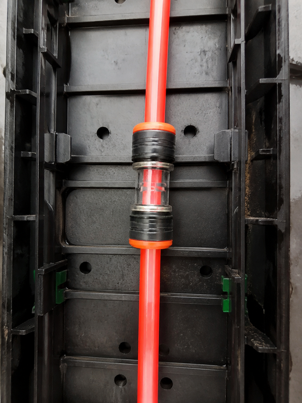
A connector is inexpensive compared with a second site visit, a lost blowing slot or a contaminated duct. A small leak reduces the air-flow pressure available to push a cable; a lip inside the bore can increase drag and damage the cable jacket. In an illustrative calculation, a crew that spends 8 minutes inspecting each joint on a 60-duct route uses 8 labour-hours, but avoiding one four-hour fault call plus traffic management usually protects the project schedule. Treat that arithmetic as a planning example, not a guaranteed saving.
The seven installation steps
1. Confirm the duct and connector specification
Read the duct marking and connector drawing together. Confirm nominal OD (for example, 7, 10, 12 or 14 mm), wall thickness, pressure class, material and whether the joint is a straight, reducer, tee or gas-block design. A straight connector is correct when both ducts share the same OD; choose a reducer only when the manufacturer lists both sizes. Do not infer fit from nominal ID or from a similar-looking pneumatic fitting. For FTTx work, verify that the connector bore and retention design are approved for the blowing pressure and cable diameter in your method statement.
2. Inspect, clean and condition the work area
Keep caps on unused ducts until assembly. Wipe the tube ends with a lint-free cloth; remove mud, gel and swarf. Check that the O-ring, collet and body are free of cuts or grit. Most push-fit designs are tool-free; use only a listed lubricant because petroleum products can swell elastomers.
3. Make a square, burr-free cut
Use a sharp microduct cutter, not side cutters. A square cut lets the tube contact the internal shoulder evenly; an angled or crushed end can roll the O-ring and create a leak path. Deburr lightly with a purpose-made reamer, then remove every shaving. Measure the cut end with a caliper if the tube looks oval. A useful field tolerance is to keep the cut face within about 1° of square and free of a visible step; follow the connector drawing when it specifies a tighter limit.
4. Mark the insertion depth
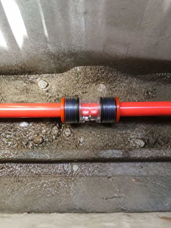
Measure from the tube end to the internal stop shown on the datasheet and mark that distance around the circumference with a fine marker. The mark is a simple quality control: after insertion it should sit flush against the collet or body reference. If the fitting has a transparent inspection window, use it as a second check. Never rely on a click alone—partial insertion can hold briefly at low pressure and then release during fiber blowing.
5. Push-fit and lock the joint
Align the tube with the fitting axis and push it through the collet and O-ring until the depth mark reaches the reference. Do not twist while pushing. Pull back gently by hand to engage the teeth, then fit any supplied locking clip. For a gas-block connector, confirm the barrier orientation.
6. Protect and support the assembled connector
Keep bending loads out of the joint. Use the manufacturer’s minimum bend radius for the duct—often expressed as a multiple of OD—and add a short, straight support section on each side in a chamber. Protect the fitting from sharp concrete edges, direct sunlight during storage and standing water where the design is not submersible. For aerial or pole routes, secure the duct so thermal movement is not transferred into the collet.
7. Pressure-test, leak-test and document
Fit calibrated gauges at the test point and pressurize with clean, dry air to the project value. Stabilize for the specified dwell period, then record starting and ending pressure, ambient temperature and section length. A soap-film check at the joint can locate bubbles, but it does not replace the project pressure test. Where the specification calls for a water test on a spare sample, ISO 1167 provides the internal hydrostatic pressure method; use the network owner’s acceptance limit for the installed air test. Depressurize safely, cap the section and release it for fiber blowing only after the result passes.
Straight, reducer and gas-block choices
Selection should follow the failure mode you are trying to prevent. Straight HDPE microduct straight connectors preserve a constant bore and are the lowest-risk option for equal-size ducts. Reducers solve a planned transition between sizes, but the step must face the fitting’s engineered taper; improvising two unrelated sizes can snag a blowing head. Gas-block connectors add an air and water barrier at building entries or chamber boundaries. The table compares the options without assuming a particular brand.
| Connector type | Best use | Performance focus | Installation/maintenance | TCO tendency |
|---|---|---|---|---|
| Straight push-fit | Same-OD HDPE duct repairs and extensions | Continuous bore, pull-out retention, air seal | Tool-free; inspect O-ring at every re-entry | Lowest unit cost; fastest field time |
| Reducer | Documented OD transition | Managed bore step and balanced retention | Requires two-size verification; spare seals useful | Moderate; avoids replacing a full duct run |
| Gas-block | Building entry, chamber or zone isolation | Air/water blocking and pressure stability | More parts; test barrier after assembly | Higher unit cost; can prevent recurring leaks |
| Mechanical screw/compression | Heavy-duty or legacy systems where specified | Torque-controlled compression | Needs torque and periodic inspection | Higher labour; useful for special constraints |
Microduct connector size guide
Nominal sizes vary by region, so procurement should specify actual measured OD and tolerance. The following guide is a starting point for common telecom ducts; confirm the manufacturer’s fit range before ordering.
| Measured duct OD (mm) | Typical connector callout | Common application | Checks before release |
|---|---|---|---|
| 7–8 | 7 mm straight | Drop microducts and compact FTTx bundles | Collet grip, cable passage, bend radius |
| 10 | 10 mm straight or reducer | Access distribution and multi-duct branch | OD tolerance, O-ring size, test pressure |
| 12 | 12 mm straight | Standard blown-fiber access routes | Insertion mark and bore alignment |
| 14–16 | 14/16 mm transition | Backbone or protected campus ducting | Transition drawing, support and pull-out test |
Standards, tests and commercial compliance
Use standards to define evidence, not as decorative badges. IEC 60794-5-1 covers outdoor ducted optical-fibre cable considerations. ISO 1167 describes hydrostatic pressure testing of thermoplastics, useful for product qualification rather than a blanket certification of an installed joint. ASTM D3350 classifies polyethylene compounds, while ASTM F2164 offers a field leak-test practice for plastic pressure piping when its scope fits.
Record the test method, pressure, dwell time and acceptance criterion. Claims such as “IP68,” “gas-tight” or “UV-proof” require a declared test scope; unsupported claims can trigger rejected submittals and rework.
Procurement checklist and supplier conversation
- Send measured OD, wall thickness, pressure and temperature range—not only a nominal size.
- Request insertion depth, bore diameter, O-ring compound, UV formulation and approved lubricant.
- Ask for batch traceability and a sample pressure/leak report.
- Plan spare O-rings and caps; define reuse after disconnection.
Microduct Connector can support configurable microduct fittings, drawings and sourcing documentation when a project has unusual OD, UV or gas-block requirements. Ask for the test evidence that matches your specification rather than accepting a generic certificate.
What should an installer record before the first blow?
A current buyer question is how to prove that a failed joint was installed correctly. Record the measured duct OD at two axes, the connector code and batch, the cut condition, insertion mark, seal inspection, test medium, test result and the joint location. That record separates a dimensional mismatch from a later route problem and gives the next crew a usable starting point.
The microduct connector range can be reviewed with the HDPE microduct options and the fiber-blowing equipment range. The combination keeps the connector, duct and installation method in one procurement record.
FAQ
Can the Hdpe Microduct Connectors be reused after the duct is disconnected?
Reuse a push-fit connector only if its maker allows it and the O-ring, collet teeth and body pass inspection. Replace nicked, flattened or contaminated seals, then repeat the pressure test.
Which material and UV rating are best for outdoor Hdpe Microduct Connectors applications?
Choose body material and elastomer rated for the site temperature and chemicals. “UV-resistant” is not a universal rating, so request the test duration and standard. For aerial sections, verify weathering and thermal movement.
Why does the Hdpe Microduct Connectors leak during or after fiber blowing?
Common causes are the wrong OD, an angled cut, incomplete insertion, a rolled O-ring or bending load. Depressurize, recut, inspect the seal and retest. Repeated batch leaks warrant supplier review.
Do you need tools or lubricant to fit the Hdpe Microduct Connectors correctly?
Most push-fit designs need only a sharp cutter, depth marker and clean cloth; no wrench is required. Use lubricant only when the datasheet names a compatible product; excess lubricant can carry grit into the collet.
How can the Hdpe Microduct Connectors join ducts with different wall thicknesses?
Use a listed reducer or transition connector covering both actual ODs and wall constructions. A same-OD straight connector is not automatically suitable when wall thickness changes bore or stiffness. Confirm the drawing, then test a representative assembly.
What temperature range should the Hdpe Microduct Connectors withstand?
Specify minimum installation and maximum operating temperatures separately; HDPE and elastomer limits can differ. Many telecom projects use around −40 °C to +60 °C, but that is not a product guarantee. Obtain the supplier’s tested range and account for solar heating.
Does EN 50411-2-8 set one pressure and hold time for every HDPE connector?
No. It is a product-specification reference for covered microduct connectors. The selected supplier instruction and the network acceptance plan define the applicable pressure, duration, medium and retest method.
What is the fastest way to distinguish a bad connector from a bad duct preparation?
Isolate the section, measure both duct ODs, inspect the cut and seal land, verify insertion to the stop, then repeat the approved leak test. Changing compressor settings before those checks can hide the original cause.
References
- ITU-T L.156: Air-assisted installation of optical fibre cablesOfficial ITU publication page; installation-method scope checked 2026-10-09.
- IEC Webstore: IEC 60794-5 microduct systemsOfficial IEC search page; verify the applicable edition for the cable system.
- ASTM D3350: Polyethylene plastics pipe and fittings materialsOfficial ASTM page; PE material classification reference.
Reliable seals are designed, not hoped for: measure the duct, seat the O-ring, test the joint, and document the result before the blower starts. When you are choosing a microduct connector for an FTTx or telecom project, contact Microduct Connector with your duct schedule and acceptance criteria for a matched recommendation.


