The term optical connector can describe two very different components: a connector that aligns optical fibres, such as an SC or LC connector, and a physical joint in the microduct surrounding a fibre cable. This guide concerns the second component. A микроканал туташтыргыч joins ducts and supports the cable-installation route; it does not make the optical connection or split an optical signal.
Choose it by function first, then duct outside diameter, internal passage, documented operating conditions and installation environment. A matching outside diameter alone is not a complete specification. Neither is a familiar colour, a transparent body or a product listing that happens to contain the words fibre optic coupler.
Do you need an optical connector or a microduct coupler?
A request for a connector for fibre optic equipment is too broad for a reliable quotation. State whether the project needs an optical termination, a duct-to-duct joint, an empty-duct closure or a seal around an installed cable. Include a route drawing or a photograph of the existing component when replacing an unidentified part.
For a duct joint, describe both duct ends and the installation location. If the joint connects equal-sized ducts, a straight coupler may be appropriate. If the outside diameters differ, a reducer needs separate specifications for each end. Neither component should be assumed to seal the annular space around a cable.
This distinction prevents misleading comparisons. An optical splitter is assessed using optical performance criteria. A microduct fitting requires dimensional, pneumatic and mechanical evidence. Comparing them under the same keyword does not help the buyer and can result in ordering a component that solves the wrong problem.
Why duct outside diameter and bore both matter when choosing a connector
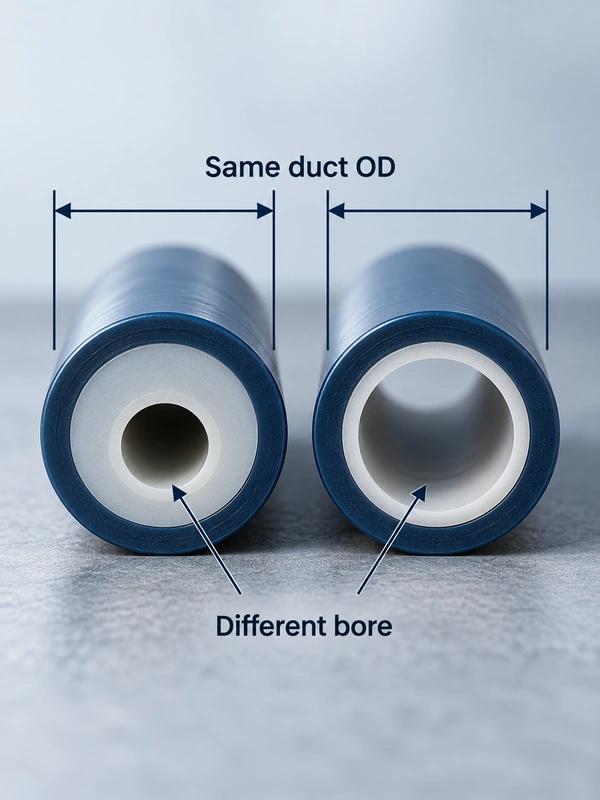
Duct outside diameter identifies the surface that a compatible push-in connector normally grips and seals. The inside diameter identifies the available passage. Measure an undamaged sample and record the manufacturer’s dimensional designation, including tolerances where available. A flattened duct end can produce a misleading measurement.
The site’s straight-coupler family lists several ducts with the same nominal outside diameter but different inside diameters. This illustrates why the two measurements must travel together in the order. The 7 mm microduct connector guide provides a useful starting point for that size family, but the project still needs the exact duct construction and cable information.
| Dimension or condition | What it controls | What to send the supplier |
|---|---|---|
| Duct OD at each end | Grip and outside seal interface | Nominal value, tolerance and duct identification |
| Duct ID at each end | Cable passage through the route | Actual bore designation and wall construction |
| Cable outside diameter | Clearance and gas-block selection | Cable manufacturer’s dimensional range |
| Connector internal passage | Possible local restriction | Drawing or confirmed minimum passage |
| Pressure and temperature | Permitted installation conditions | Approved operating envelope for the assembly |
Do not measure only the visible collar opening and call it the connector bore. Hidden shoulders or a reducer transition may determine the limiting passage. Obtain a drawing or written confirmation rather than probing a sealed product in a way that could damage its internal components.
Will the fiber cable fit through every duct and connector?
A cable must pass through every duct section, joint and transition. A generous bore at the starting chamber does not compensate for a smaller downstream section. Record reducer locations and verify the minimum route passage against the cable and installation-system requirements. There is no universal cable-to-duct ratio that can be applied without those requirements.
Consider a hypothetical replacement where the existing duct and new duct share the same outside diameter but have different wall thicknesses. The connector may accept both ends mechanically, while the cable encounters a narrower passage beyond the joint. The purchasing decision must therefore separate physical fit from route suitability.
Bends, unsupported joints and damaged duct ends also affect passage. A pressure-tight joint can still contain an obstruction. Plan the route’s permitted continuity or passage check separately from its leak test, using the network owner’s procedure and appropriately rated equipment.
When to use a straight coupler, end stop or gas block
A straight coupler joins compatible ducts. An end stop closes an unused duct. A gas block provides a seal around the installed fibre unit or cable within its stated size range. Emtelle’s gas-block documentation explicitly distinguishes the tube joint from the low-pressure seal of the space around the fibre unit.
Ал gas-block microduct connector guide explains when this additional cable seal is required. For an empty branch awaiting a later connection, an appropriately sized microduct end cap serves a different purpose. Do not try to pass a cable through an ordinary end stop and assume the altered part remains sealed.
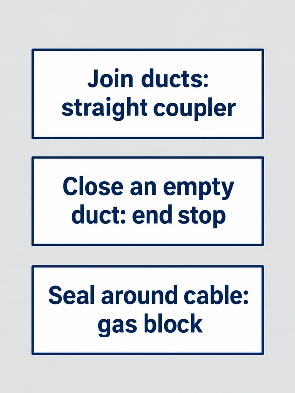
| Required job | Candidate component | Separate question to resolve |
|---|---|---|
| Join equal duct sizes | Түз кошугуч | Are both bores and duct materials approved? |
| Join different duct sizes | Reducer coupler | Can the cable pass the smaller section? |
| Close an empty duct | End stop | What pressure and environmental conditions apply? |
| Seal around installed cable | Gas or water block | Does its cable seal cover the actual cable diameter? |
A locking clip or cover may protect a release mechanism, but it does not create a cable seal. Document the component’s role in the route so that future maintenance staff do not remove a sealing device under the assumption that it is only a protective accessory.
Which pressure rating applies to the microduct connector?
Blowing pressure, working pressure, proof pressure and burst pressure describe different conditions. A gas-seal rating is another separate property. Emtelle’s published gas-block datasheet illustrates this distinction by listing gas sealing separately from its pressure information for fibre installation. Those values apply to its named products, not to every similarly shaped connector.
Ask for a current model-specific datasheet covering the proposed temperature, duct material and test conditions. When a catalogue contains inconsistent pressure figures, obtain clarification before ordering or testing. Choosing the larger number because it appears in a headline is not a defensible engineering decision.
Hexatronic’s MPB30601+ page also separates construction, application and test information. Its specified external-cover configuration is relevant to direct burial. These are useful examples of the evidence to request, but another manufacturer’s results do not establish the capability of an ANMASPC product.
Do microduct connectors need BSP or NPT thread seals?
Ordinary push-in microduct joints do not need BSP or NPT thread sealant at the duct entry. They depend on the approved duct size, end condition, insertion and internal sealing design. Adding tape around the duct can interfere with seating and does not turn an incompatible tube into a compatible one.
A blowing head or test adapter may include a threaded connection elsewhere in the setup. Identify that interface separately. Confirm the thread standard, sealing arrangement and tightening instruction from the equipment manufacturer. Keep sealant debris out of the cable passage and never mix thread types simply because they start to screw together.
What to inspect and record after installing a microduct connector
Prepare the duct with the specified cutting tool, keeping its end square, round and clean. Follow the connector’s insertion and retention instructions. Support the route so it does not pull sideways on the fitting, and install required covers or locks. Before touching a pressurized joint, isolate the system and verify that stored pressure has been released.
Record the installed connector, duct sizes on both sides, cable details where relevant, location and acceptance results. These details matter when an upgrade adds a larger cable or changes a duct section. The existing connector may remain serviceable, but compatibility needs to be reassessed against the new route conditions.
Көп берилүүчү суроолор
How do I install a microduct connector without damaging the tube?
Use the approved cutter, inspect the end for scratches and ovality, and insert it according to the connector instructions. Protect clean ends from grit. If a damaged section is removed, confirm the remaining length still allows an aligned, supported joint.
Can a microduct connector be disconnected and reused?
Only if its manufacturer permits reuse and the body, grip and seals remain acceptable. Release pressure first. Inspect the duct contact area and follow any requirement to cut back or replace the tube; do not assume a previously used end is undamaged.
Which seal should be used on a threaded microduct test adapter?
First establish whether there actually is a threaded side. A typical push-in duct joint has none. For a separate threaded adapter, follow its specified thread and sealing system; instructions for an optical connector or another fitting family do not apply.
What should I measure before ordering a replacement microduct connector?
Record duct OD and ID on both sides, cable diameter when relevant, connector identification and installation environment. Include tolerances and pressure-temperature requirements. A photograph helps identify the part but cannot replace a dimensional specification.
Why might a duct release under vibration?
Possible causes include incomplete insertion, an unsuitable diameter, damaged retention components, accidental collet operation or route tension. Isolate and inspect before assigning the cause. A locking accessory cannot compensate for a fundamentally incompatible or damaged joint.
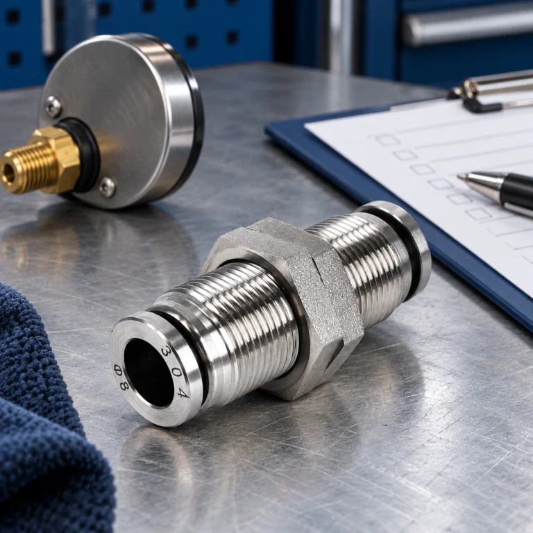
Is a plastic, brass or stainless steel fitting suitable for this microduct?
Select the documented assembly for the route and medium. Material labels alone do not establish cable passage, retention, pressure suitability or environmental durability. A general pneumatic metal fitting is not automatically a substitute for a purpose-designed microduct coupler.
Деректер
- Hexatronic, MPB30601+ microduct connectors and end stops: component functions, construction and application conditions.
- Emtelle, Gas Block Connector: sealing between tube, connector and fibre cable.
- Emtelle, Gas Block Connectors datasheet, Issue 5: distinct tube and fibre-unit interfaces and model-specific performance information.
Summary
Order a duct connector by its job and the complete route specification. Confirm both duct diameters, cable clearance, pressure conditions and exposure, then verify installation and testing requirements. Keeping optical terminations, duct joints and cable seals distinct prevents the most basic selection mistake before installation begins.
For sourcing, submit those details with an enquiry for the straight microduct coupler family. Request the exact size drawing and applicable test documentation rather than relying on the family photograph or a general catalogue description.