
A microduct connection that holds air during cable blowing can still leave a migration path around the installed cable. At a building or optical distribution frame entry, that difference changes the purchasing decision: does the route need a duct joint, an occupied-duct seal, or a separate penetration system? Choosing by nominal duct size or a single pressure figure can leave those functions unresolved and create avoidable investigation and replacement work. Moisture near a connector also does not identify where it entered the route. This guide explains how to separate the interfaces, select the cable seal, check the assembly state, and commission the connection without confusing blowing capability with sealing performance.
The short answer is that a gas block microduct connector seals the pathway around a compatible installed cable as well as connecting to the duct. The current Waterproof Air Gas Block product data distinguishes 10 bar blowing pressure from cable sealing up to 0.3 bar. These describe different functions and assembly states, not interchangeable test pressures. Verify the exact duct and cable combination, operating sequence, medium, and acceptance procedure before ordering. A gas block within the microduct is not, by itself, an approved wall penetration seal, firestop, or universal hazardous-gas barrier.
Which pathway needs sealing at the entry point?
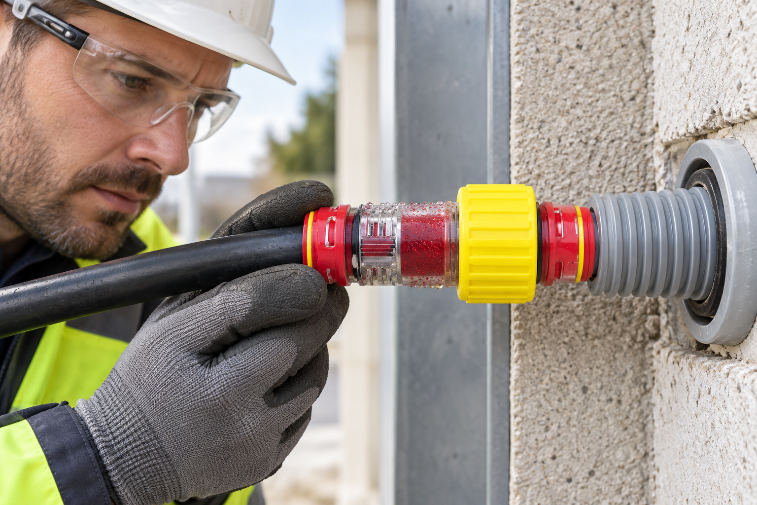
Separate three interfaces. A duct-to-body seal closes the connection around the tube. A cable seal closes the annulus between the cable jacket and its surrounding passage. A building-entry system addresses the penetration through the wall or other boundary. A Түз микродукт туташтыргыч provides a joining function; do not assume it also seals the cable annulus.
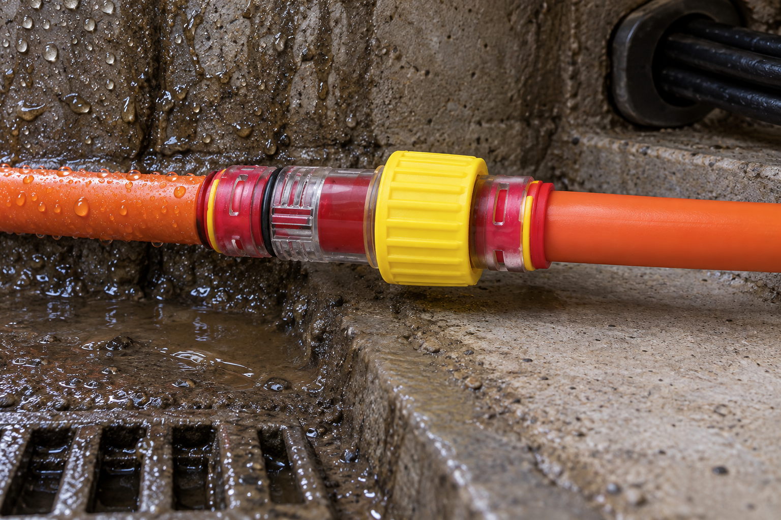
Water can enter elsewhere and travel along the duct, while moisture outside the assembly may have a different origin. Investigate upstream openings, other joints, chamber conditions, and the wall penetration before blaming the wet connector. Isolate the suspected pathway using the approved inspection or test method. An empty-duct test does not establish the performance of the final occupied cable annulus.
| Component | Primary task | Selection boundary |
|---|---|---|
| Түз кошугуч | Join compatible ducts | Does not automatically seal around a cable |
| End cap or stop | Close an unused duct end | Not an occupied-duct annular seal |
| Gas block | Seal around an installed cable | Requires the correct cable range and assembly state |
| Wall-entry or firestop system | Address the building penetration | Needs independent design and applicable approval |
Ал end-stop versus gas-block comparison helps resolve whether the duct will remain vacant or carry a cable.
When should the cable seal be opened and activated?
For the Oulu family cited above, the published sequence is to keep the connector open for cable blowing and then rotate the ring to seal. Record that as a product-specific instruction, not a universal rule for every gas-block design. Other assemblies may use different mechanisms or require different installation states.
Prepare the duct, confirm full seating, and inspect the cable jacket before activating the seal according to the supplied instructions. The product page lists two separately ordered locking clips to prevent self-release. Confirm whether they are included in the order; a clip cannot correct the wrong duct size, damaged tube, incomplete insertion, or incompatible cable seal.
FCST’s 2025 connector installation instruction illustrates an important distinction: a duct can be gripped without being fully seated. Its guidance includes clean, round, undamaged tube, square cutting, burr removal, and depressurization before release. Use these as an external maker’s installation example, while following the exact Oulu assembly instructions rather than importing another supplier’s tolerances.
How should blowing and cable-sealing pressure be checked?
Keep the cable sealing pressure separate from the blowing pressure on the specification sheet. The cited family’s 10 bar statement concerns blowing; its cable-sealing statement is up to 0.3 bar. Do not test the activated cable seal at 10 bar or derive proof, burst, or service ratings from either figure. Confirm the selected code’s documented limit and approved test method, because a family page does not establish every model combination.
A proposed test needs the assembled state, duct dimensions, cable outside diameter, medium, pressure, stabilization and hold periods, and acceptance criterion. Those conditions must come from the applicable manufacturer and project procedure, not a generic article. Use suitable instruments, account for temperature effects as that procedure permits, and depressurize before adjustment. A visual insertion check is useful, but it does not replace leakage testing.
| Observation | Possible investigation area | Next action |
|---|---|---|
| Leak at duct-to-body interface | Tube dimensions, cut, seating, damage, or side load | Depressurize and inspect the tube and connector |
| Leak along the cable annulus | Cable range, jacket condition, seal fit, or activation | Check the exact seal and installed cable combination |
| Water appears near the entry | Upstream route, chamber, joint, or wall penetration | Trace the pathway before replacing a component |
| Pressure changes without a visible leak | Temperature, stabilization, instrumentation, or leakage | Review the test conditions before judging the assembly |
What evidence is needed for outdoor use and future repairs?
EN 50411-2-8:2009 covers initial dimensional, optical, mechanical, and environmental requirements for installed blown-fibre microduct connectors in protected installations. Its catalogue scope excludes connectors intended for direct sunlight. Citing that standard therefore does not establish an exposed product’s UV suitability, direct-burial capability, or lifetime.
For sunlight exposure, request evidence tied to the actual material and component. ISO 4892-1:2024 provides general guidance on laboratory light-exposure methods and interpreting accelerated weathering data. It is not a product certificate or a fixed conversion from test hours to field years. Verify the site’s temperature, moisture, chemicals, protection, and access conditions separately.
IEC 60794-5:2014 concerns microduct optical fibre cables, fibre units, microducts, and protected microducts intended for blowing. The newer IEC TR 63431:2025 supplements that context with guidance on design types, colour codes, repairs, environmental expectations, and installation. Use this Technical Report to frame route design and repair planning, not as a connector rating or a substitute for test evidence.
What should procurement approve before installation?
Specify duct OD, ID or wall construction, and the cable’s actual outside-diameter range separately. Request a dimensioned drawing and confirmation of the supplied sealing element; nominal duct size alone cannot establish cable compatibility. Confirm the required clips, protection, ring sequence, and access for later inspection.
For gas-water block selection, Zhejiang Oulu / ANMASPC’s transparent PC family lists microduct OD 4-16, but the exact duct-to-cable combinations still require confirmation. Record the assembly code, lot, geometry, installed state, test conditions, results, and any correction. Budget for this documentation and access work rather than comparing component prices alone; uncertain fit can create replacement and recommissioning costs.
What do installers need to know before acceptance?
How does a Gas Block Microduct Connector prevent moisture migration into a conduit?
It seals the specified duct interface and the passage around a compatible cable. That does not resolve every route ingress source; confirm the installation and investigate other entry paths.
Is a transparent body useful when checking a Gas Block Microduct Connector installation?
Yes, it can help reveal insertion and visible contamination. Transparency cannot demonstrate leak integrity or correct seal activation, so complete the specified acceptance checks.
What outdoor temperature and UV conditions should the Gas Block Microduct Connector handle?
The exact assembly must suit the site’s installation and service conditions. Request model-specific temperature and exposure evidence; do not infer sunlight suitability from transparency or a standards reference.
How often should a gas-water block connector be inspected?
Set a risk-based interval with the operator, considering access and consequences of migration. Include checks after cable work, repair, flooding, or abnormal movement rather than assuming a universal schedule.
What contaminants does the Gas Block Microduct Connector block in a microduct?
Only claim the media and conditions supported by its documented sealing performance. Chemical compatibility, hazardous-gas protection, and permeation resistance require separate evidence.
Should the gas or water seal be activated before fiber installation?
The cited Oulu design is open for blowing, then sealed by rotating its ring. Follow the actual supplied model’s procedure; this sequence is not universal across gas blocks.
What should close a spare duct without a cable?
Use a compatible microduct end cap or specified vacant-duct closure. An occupied-cable seal should not be assumed to seal an empty bore.
Can a gas block be reused after cable replacement?
Only with exact manufacturer approval and inspection of the body, retention parts, and seal. Reconfirm the replacement cable range and retest the final assembly; there is no universal reuse-cycle allowance.
Which sources define the verification boundaries?
- NEN: EN 50411-2-8:2009 microduct connector scope
- FCST: Microduct connector installation instruction, August 2025
- IEC 60794-5:2014: Microduct optical fibre cabling specification
- IEC TR 63431:2025: Microduct technology design and repair guidance
- ISO 4892-1:2024: Laboratory light-exposure and weathering guidance
How can the final decision avoid an incomplete entry seal?
Choose the gas block by the pathway it must seal, not by the largest pressure printed beside it. First separate duct joining, cable-annulus sealing, and the building penetration; then confirm duct geometry, cable range, exposure, and the supplied assembly’s operating sequence. Keep blowing and cable-sealing acceptance as distinct activities, and never apply the blowing pressure to the activated cable seal. If migration persists, investigate the route instead of assuming the nearest wet joint is responsible. Repair planning should preserve access and require a documented check of the final occupied state. Provide the actual duct, cable, and entry details when requesting drawings and model-specific test information before purchase.


