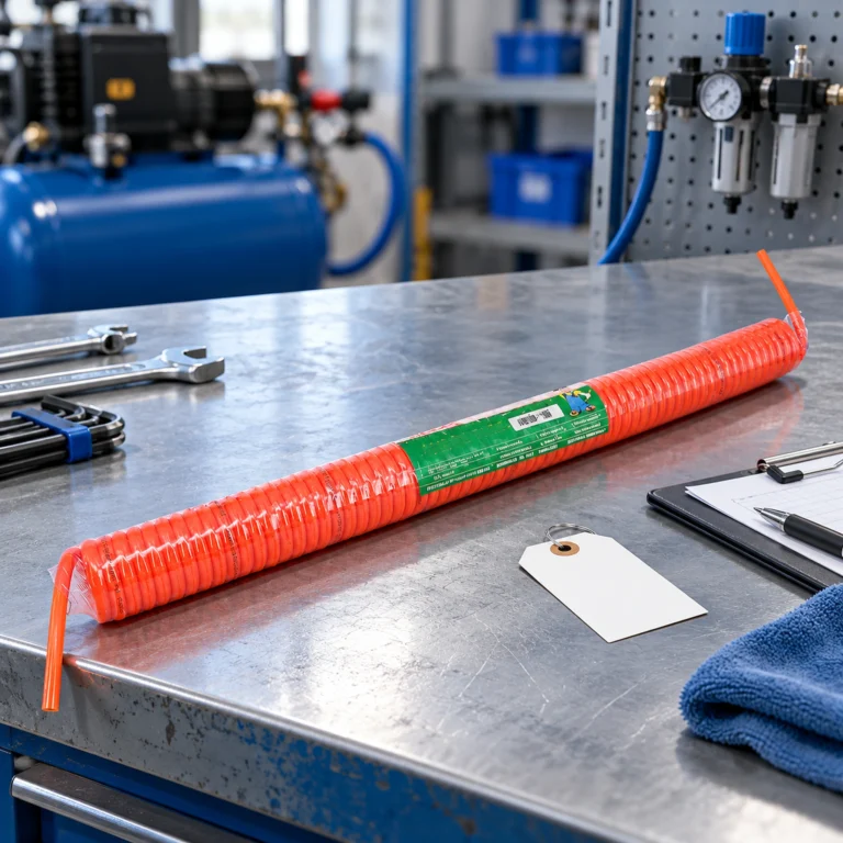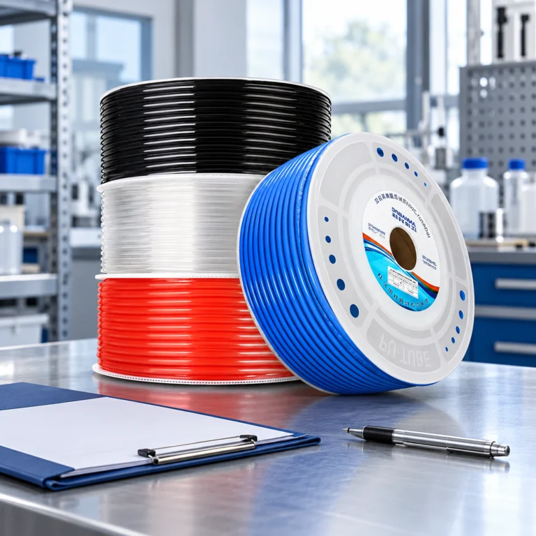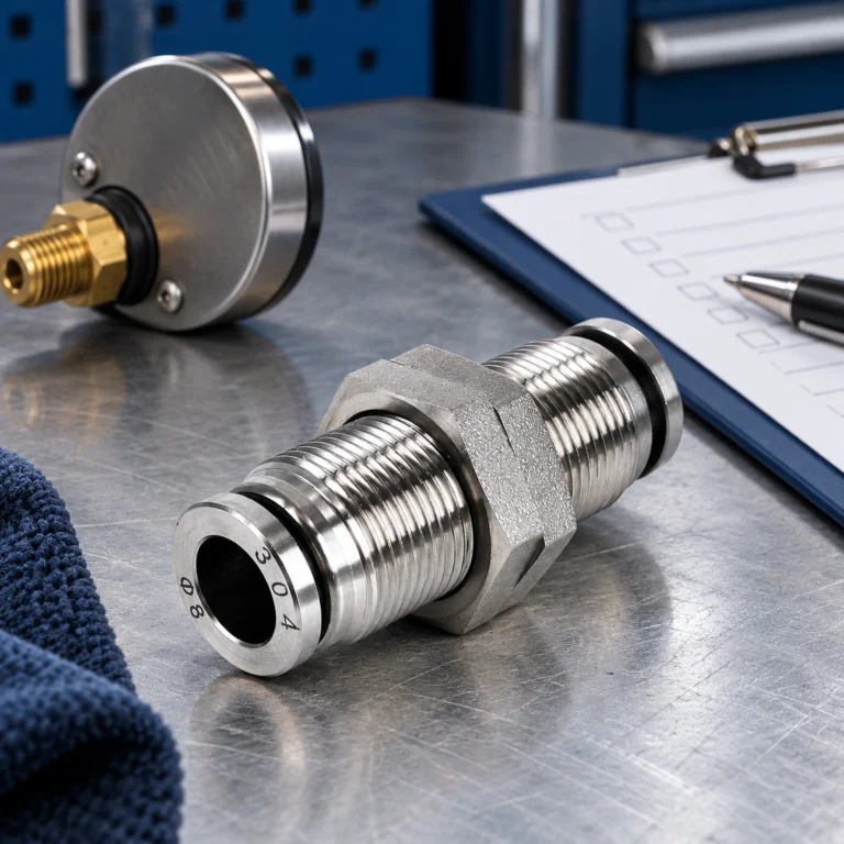
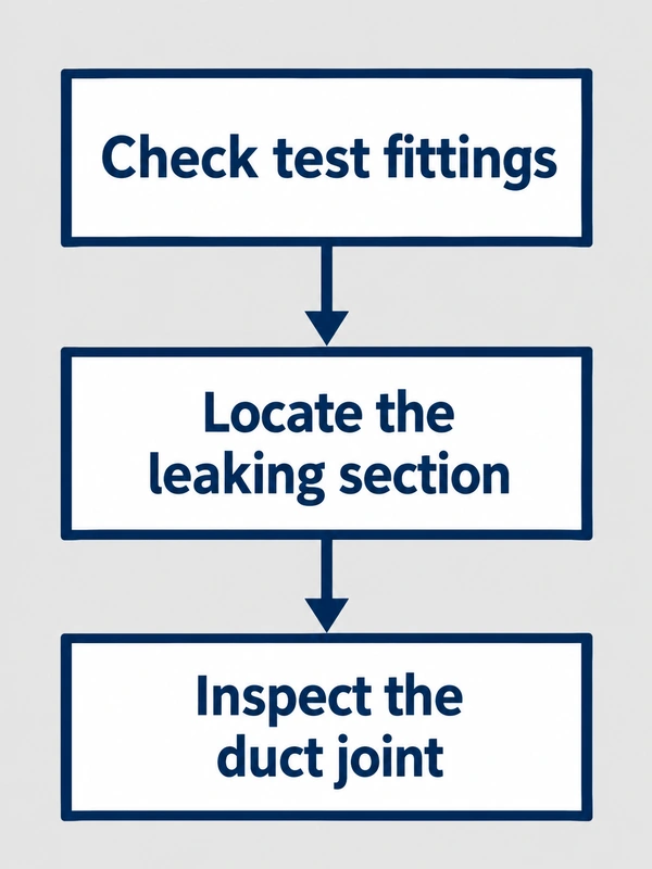
A leaking fiber optic duct connector can delay cable installation, but replacing the first joint that hisses is not always the complete repair. The test adapter may leak, the duct may be scratched farther inside the fitting, or the route may pull the joint out of alignment. Work through six checks: the test setup, duct size, cut condition, insertion, seal condition and mechanical loading.
These checks apply to the physical duct joint, not to an optical plug. They do not define a universal pressure-test procedure. Use the network owner’s approved method, the exact component ratings and competent personnel. Isolate and depressurize the assembly before cutting duct, operating a release collar or dismantling any connection.
Check 1: Is the leak in the test adapter or the duct connector?
Identify the section under test and every temporary connection attached to it. The regulator, gauge, hose, test adapter and far-end closure can all affect the result. Confirm their ratings, condition and sealing method before treating a falling pressure reading as proof that a buried duct connector has failed.
Where the approved procedure allows it, investigate a smaller isolated section to narrow the fault location. Record initial conditions and allow the specified stabilization period. Air temperature changes after filling can change the pressure reading even without a leak. Do not repeatedly increase the pressure in an attempt to force an ambiguous result into a pass or fail.
An empty-duct end stop also deserves attention. Use the microduct end-cap troubleshooting guide when the temporary closure moves or leaks. A test cannot establish joint performance if the closure at the other end is unsuitable.
Checks 2 and 3: Does the duct fit, and is the tube end damaged?
The second check is dimensional. Match the actual duct outside diameter, tolerance and material to the connector’s approved specification. Measure an undamaged section and check more than one orientation if ovality is suspected. A nominal size printed on an old order is not enough when the supplied duct or connector has changed.
The third check is the end condition. A square cut preserves the intended seating geometry. A slanted, crushed or burred end can prevent proper insertion or leave a rough cable passage. Inspect the outside surface in the seal contact region as well as the cut face. A longitudinal scratch can remain relevant even when the visible edge looks neat.
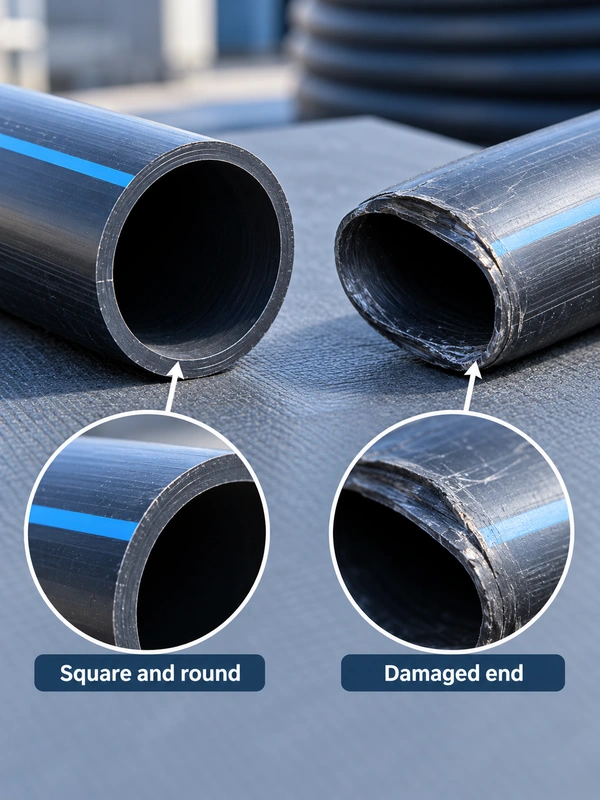
| Текшерүү | Evidence to collect | What the observation does not prove |
|---|---|---|
| Duct diameter | Identification and measurements on sound material | A similar-looking size is interchangeable |
| Roundness | Condition around the full circumference | One diameter reading establishes a round end |
| Cut geometry | Square, clean, undeformed end | A neat cut guarantees internal seating |
| Outside surface | Scratches, dirt and grip damage near the seal | An undamaged cut face means the sealing surface is sound |
If the duct is damaged, cut back only under the approved repair method and leave enough length for a supported joint. Do not shave the tube outside diameter to make it fit or build it up with tape. Both actions change the interface that the connector was designed to seal and retain.
Check 4: Is the microduct fully inserted and securely held?
Full insertion means the position specified by the connector manufacturer, not simply the point where resistance is first felt. Follow its depth indication or marking method. A transparent body can assist observation, but visibility depends on the product design and does not replace the prescribed installation check.
Use the manufacturer’s retention check and fit required clips or covers. Do not apply an arbitrary pull load to a pressurized connection. If the duct moves unexpectedly, isolate the assembly and investigate size, seating, grip damage and route tension. Repeatedly pushing the same damaged end back into the fitting may preserve the original defect.
Hexatronic’s MPB30601+ documentation describes pressure seals and a separate gripping mechanism. This illustrates why sealing and retention should be checked independently. A joint can appear mechanically secure yet leak, or seal briefly while its duct retention remains unsuitable for service.
Check 5: Are dirt or damaged seals causing the connector to leak?
Grit carried into a connector can affect seating or damage a sealing surface. Keep spare connectors and prepared duct ends protected until assembly. Follow the manufacturer’s cleaning instructions, including any restrictions on solvents and lubricants. An unapproved cleaner may attack the body or seal material even if it removes visible dirt.
Replace cracked, distorted or visibly damaged components according to the service policy. Do not assume an internal O-ring is user-serviceable or substitute one selected only by approximate diameter. Seal material, cross-section and installation condition all matter, and many small fittings are supplied as complete replacement units.
A connector used to join ducts is also different from a cable-entry seal. Emtelle describes a gas block as sealing the space between the connector, tube and fibre cable. The guide to locking clips versus gas blocks helps distinguish mechanical retention from that additional sealing function.
Check 6: Is the duct pulling on the connector or pressing its release collar?
A correctly assembled connector can be undermined by the route around it. Look for unsupported duct weight, tight bends immediately beside the body, tension from insufficient slack and contact that presses the release collar. Inspect the final installed position, not only the straight configuration used on the workbench.
Support the ducts using the approved route design. The joint should not serve as a hinge for forcing misaligned sections together. Where an external cover is required, confirm the correct version and fit it without trapping dirt or preventing inspection. A cover cannot correct a wrong duct size or damaged seal.
For an unused branch, specify an appropriate duct end stop instead of improvising a closure. Mark which branches are empty and which contain cable so later technicians do not mistake a temporary closure for a completed cable-entry seal.
How to retest a microduct joint after fixing a leak
After correcting the identified fault, repeat the same approved test with comparable temperature, equipment and section boundaries. Record the actual pressure, duration and acceptance criterion from the project procedure. This article deliberately supplies no generic test pressure: the permissible value must come from the assembled system and its approved method.
The US Department of Energy’s compressed-air guidance recommends identifying, tracking, repairing and verifying leaks. That maintenance principle is useful here, but its industrial-air examples are not a telecom duct acceptance standard. Keep the distinction clear when writing the commissioning record.
| Result after repair | Likely next investigation | Record to retain |
|---|---|---|
| Leak remains at the same joint | Compatibility, hidden damage and replacement policy | Part identification and repaired interfaces |
| Pressure changes with no localized leak | Temperature, gauge, adapters and section boundaries | Conditions and equipment details |
| Joint passes but cable passage is restricted | Bore, burrs, reducer transitions and route bends | Separate passage-check result |
| Fault returns after placement | Support, tension, cover and collar contact | Final installed configuration |
Do not equate a successful duct leak test with guaranteed cable-blowing distance. Passage, cable properties, route geometry and installation equipment still need assessment. An airtight joint is one requirement within the route, not a performance prediction for the whole installation.
Көп берилүүчү суроолор
Which sealing method applies to a threaded duct connector?
Confirm that the leaking interface is actually threaded. Most push-in duct entries use their internal sealing design. A separate threaded test adapter requires its own thread and seal specification; tape around the duct is not an acceptable substitute for correct fit.
Which duct dimensions are needed for a replacement connector?
Record both duct outside diameters, their bores, duct material and connector identification. Include cable diameter if selecting a cable seal. Measure undamaged material and obtain a product drawing when the internal passage or reducer transition matters.
Why does a microduct pull out of its connector when the route moves?
Inspect incomplete insertion, damaged grip components, unsuitable dimensions, unsupported loads and accidental collet contact. Depressurize first. Correct the underlying cause and follow the specified retention check; adding a clip does not make an incompatible joint suitable.
Is a metal fitting less likely to leak than a plastic fitting?
Not necessarily. The complete design, compatible duct, seal condition and installation determine suitability. A metal pneumatic fitting may have an unsuitable bore or gripping arrangement for a fibre duct. Select by documented application rather than body material alone.
How do you check airflow and restriction through a microduct connector?
Follow markings and instructions for any directional component, especially reducers or specialized assemblies. Use the approved route test to investigate restriction. Do not infer usable airflow or blowing performance solely from a static pressure-hold result.
When should a microduct connector with a damaged collet or seal be replaced?
Cracks, distortion, visible seal damage, loss of retention or repeated leakage after correct installation justify removing the suspect component from service. The manufacturer’s policy determines whether individual parts can be replaced or the entire connector must be renewed.
Деректер
- Hexatronic, MPB30601+ connectors and end stops: sealing, retention and external-cover functions.
- Emtelle, Gas Block Connector: cable-annulus sealing as a distinct function.
- US Department of Energy, Minimize Compressed Air Leaks: leak management and verification principles, not telecom acceptance limits.
Summary
Find the leak systematically: establish a reliable test setup, verify size and cut quality, check insertion and seals, then remove route loads. Retest the repaired section under documented conditions and keep passage checks separate. This approach gives the next installation crew a usable record instead of an unexplained replacement part.
When replacement is needed, compare the FTTH microduct straight quick coupler against the measured duct, location and required test conditions. Request the specific size and current installation instructions with the quotation.