
A connector that grips a microduct in a chamber is not automatically suitable for placing directly in soil. For contractors and buyers, the difficult decision is whether the ordered fitting and the duct around it are both intended for the proposed buried route. A familiar nominal size, an ingress-protection claim, or a successful empty-duct pressure check cannot answer every part of that question. Once the trench is backfilled, correcting an unsuitable joint also means regaining access. The useful starting point is therefore the exact connector code, duct construction, and installed configuration, not a generic description such as waterproof. This guide separates burial selection, bore transitions, exposure evidence, and the release checks needed before the joint becomes inaccessible.
The short answer is to select a direct buried microduct connector only when its exact code has documented suitability for the intended duct and burial conditions. Confirm duct outside diameter, inside diameter and wall construction separately, then establish preparation and acceptance procedures. EN 50411-2-8:2009 covers initial requirements for installed blown-fibre microduct connectors, but its scope excludes connectors intended for direct sunlight; citing it does not certify a particular fitting. A chamber coupler, cover shell, or IP statement alone is insufficient evidence of direct-burial suitability. Obtain the applicable drawing, instructions and test evidence before approving the purchase.
What makes a connector and duct suitable for direct burial?
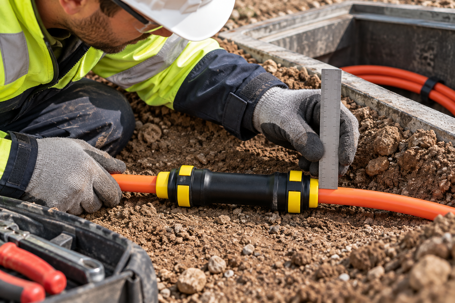
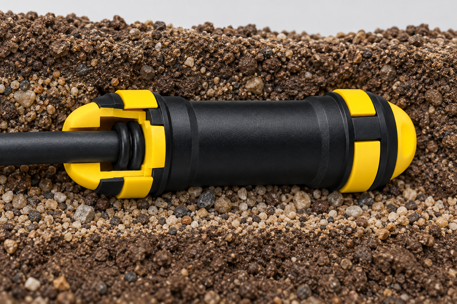
Direct burial is a system decision: a connector cannot compensate for unsuitable duct construction. As an attributed manufacturer example, Sanbor’s connector application guidance identifies particular DB-use families, including CV4580-V4580 and CV4750-V4750. It also warns against burying thin microduct, which can fail even when the connector performs correctly. These are Sanbor-specific statements, not approval of Oulu parts.
For the proposed assembly, ask which exact part code is intended for direct burial, which duct construction was assessed, and whether any protective components are required. Evidence should identify the tested geometry and assembly state. A family label does not establish that every size, revision, tube wall, or installation arrangement has the same suitability.
A locking clip addresses inadvertent release; it does not correct the wrong duct diameter, a damaged tube or a faulty seal. An external cover has another role and should not be treated as a pressure or gas seal. The related cover-shell troubleshooting guide helps distinguish protection from sealing.
How do duct dimensions and reducer transitions affect selection?
Match each connector end to the measured duct OD, then check ID and wall construction. Equal outside diameters do not guarantee equal bores. Request a dimensioned drawing rather than inferring fit from a nominal label. The push-fit connector size and application comparison provides related selection context.
For a direct-bury microduct coupler, a reducer must be an approved transition, not an improvised seal around the smaller duct. The official EN 50411-2-8:2009 catalogue scope notes that reducer or enlarger transitions may require manual feeding because of the pressure gradient at the size step. A connector that accepts both tubes therefore does not guarantee uninterrupted blowing through the transition.
| Proposed connection | Cosa verificare | What cannot be assumed |
|---|---|---|
| Same-size buried joint | Exact DB code, duct OD and construction, bore alignment | All couplers of that nominal size are burial-rated |
| Reducer joint | Both end dimensions, internal transition, planned feeding method | Different bores blow like a continuous same-size duct |
| Covered chamber coupler | Approved location and purpose of the cover | The cover upgrades the coupler to direct-burial service |
| Occupied duct seal | Compatible cable seal and separate operating state | A straight coupler seals the annulus around a cable |
Which pressure and exposure claims need separate evidence?
Keep working, proof, burst, cable-sealing and route-acceptance pressures separate. A test value without its medium, procedure, assembly state and acceptance criterion is not a usable installation limit. This article assigns no generic pressure, material, OD range or IP rating to the direct-bury family; obtain those details for the supplied code.
EN 50411-2-8 concerns initial dimensional, optical, mechanical and environmental requirements, with protected installations described in its scope. Because direct sunlight is excluded, a standards reference cannot also prove UV suitability. For exposed storage, installation or service, request separate evidence matching those conditions. ISO 4892-1:2024 provides general guidance on laboratory light-exposure methods and interpreting accelerated-weathering data. It does not certify a product or supply a fixed hours-to-field-years conversion.
The official IEC TR 63431:2025 synopsis describes guidance on microduct design types, colour codes, repairs, environmental expectations and installation. It supplements the microduct sections of IEC 60794-5. Use that Technical Report as system-planning context, not a universal component rating or replacement for connector-specific evidence.
What should installers check before releasing a joint for backfill?
Prepare the tube according to the exact maker’s instructions. As an external example, FCST’s installation instructions, published 22 August 2025, call for clean, round, undamaged duct, a square cut and burr removal. They warn that a tube can be gripped without being fully seated, causing leakage. Their transparent-body checks and clip instructions are product-specific examples, not universal dimensions or Oulu test results.
Use the specified insertion reference, clip and preparation method. Depressurize before release or investigation. Do not improvise with tape, sealant or lubricant unless the maker approves the material and procedure. If an interface fails inspection, correct it before the agreed retest rather than relying on burial to restrain it.
| Record item | Product evidence | Before-backfill release evidence |
|---|---|---|
| Identity and fit | Code, drawing, approved duct geometry | Installed code or lot, measured geometry, route location |
| Assembly | Preparation, insertion and accessory instructions | Seating, condition and specified accessory checks |
| Testing | Declared ratings and relevant test conditions | Medium, procedure, instrument, result and corrections |
| Release | Permitted application and limitations | Acceptance decision, date and responsible approver |
This direct-burial connector acceptance record is practical traceability advice, not a claimed universal statutory form. A datasheet describes the product; a release record shows what was installed and accepted. Identify local interface checks separately from route tests, and do not treat an empty-duct result as proof of an occupied cable-annulus seal. Where that distinction matters, compare end stops and gas-block connectors.
What else should installers ask before approving a buried joint?
Why does a direct buried microduct connector leak during or after fibre blowing?
Investigate duct dimensions, cut quality, contamination, insertion and damage before blaming the fitting. Depressurize and isolate interfaces; water found at a connector does not by itself identify where it entered the pathway.
Are tools or lubricant needed to fit the connector correctly?
Push-fit retention does not eliminate cutting, measurement or test equipment. Follow the supplied instructions, and use lubricant only if the maker approves it for that exact assembly.
Can the connector join ducts with different wall thicknesses?
Possibly, if the exact connector accepts both ODs and the duct constructions are approved. Check the resulting ID transition separately, including whether the cable and feeding method can accommodate it.
What temperature range should the connector withstand?
Confirm installation and service conditions against the exact product’s documented limits. Do not transfer another size’s temperature range or assume that buried service removes every exposure concern.
How can installers visually check full insertion?
Use the maker’s insertion mark or reference. A transparent body may help on applicable designs, but visible grip alone is not proof of seating or successful acceptance testing.
When should the seals or connector body be replaced?
Follow the maker’s inspection and replacement criteria for damage, contamination, loss of grip or failed sealing. Reuse requires exact-model approval, inspection and retesting; there is no universal permitted reuse count.
Can an ordinary chamber connector be buried inside a cover?
Not without documented approval of that assembly for direct burial. External protection and connector qualification are different questions, so confirm both rather than inferring approval from appearance.
Does a passed pressure test remove the need for a release record?
No. Without the code, geometry, assembly state, procedure and result, the test cannot be reliably tied to the buried joint. Record corrections and acceptance before access is lost.
Which sources support the selection checks?
- NEN: EN 50411-2-8:2009 official scope, sunlight exclusion and reducer limitation.
- Sanbor: connector applications and the thin-microduct burial warning.
- ISO: ISO 4892-1:2024 laboratory light-exposure guidance.
- IEC: IEC TR 63431:2025 microduct technology guidance synopsis.
- FCST: Installation Instruction For Microduct Connector, 22 August 2025.
How should buyers make the final burial decision?
Approve the assembly, not the phrase direct bury. Start with the duct construction and route conditions, identify the exact connector code, and reconcile its drawing and instructions with the proposed OD, ID and transition. Then separate product ratings from field acceptance and establish what evidence must be recorded before backfill. Neither a gripping tube nor a generic IP claim is a reason to skip that sequence. If sunlight or a reducer is involved, resolve its specific limitation before scheduling blowing or closing the trench. Oulu’s direct-bury connector product page is a starting point for a code-specific enquiry: provide the duct geometry, construction and installation conditions, and request the applicable documents before releasing the order.


