When a maintenance engineer in Ningbo reviews an automated assembly cell, a small air leak at a fitting can become a visible failure: a gripper misses its repeatable stroke, the line pauses, and the first instinct is to blame the actuator. In this illustrative planning scenario, the reversal is important. The root cause may be component selection, tube routing, pressure stability, or maintenance access rather than a defective cylinder. That is why the future of pneumatic products in automation is less about promising a universally “smart” component and more about integrating a correctly specified air circuit with controls, sensors, and disciplined maintenance.
Pneumatic products remain useful for fast, repeatable motion and simple force transmission, but their future value depends on system design. ISO 4414:2010 addresses safety requirements for pneumatic systems and components; it is not a blanket efficiency certification. Start with the load, cycle, pressure, environment, and safe state, then measure leakage and pressure behavior before choosing connected monitoring or a different motion technology.
Where do pneumatic products fit in modern automation equipment?
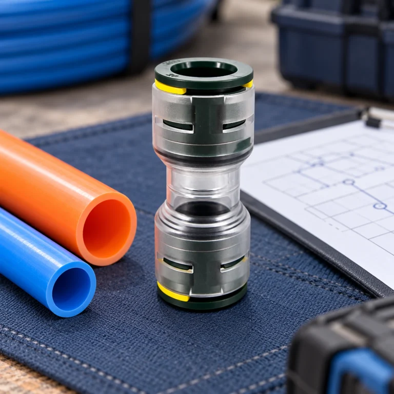
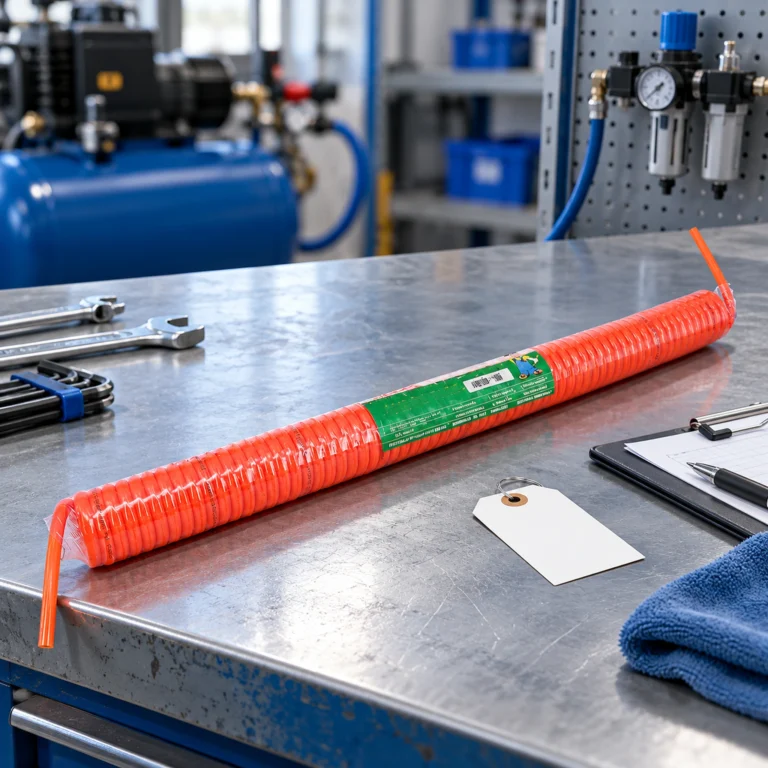
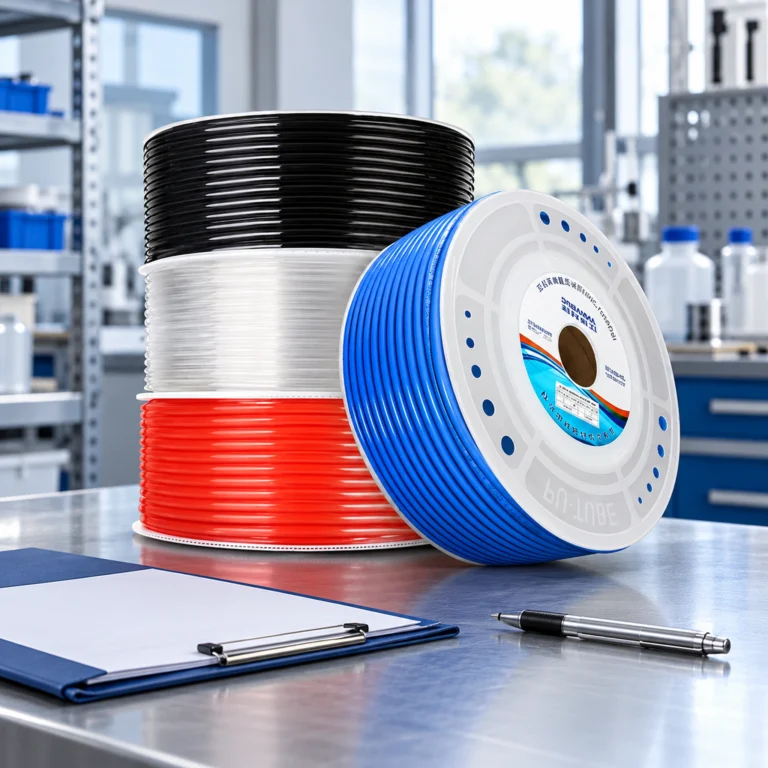
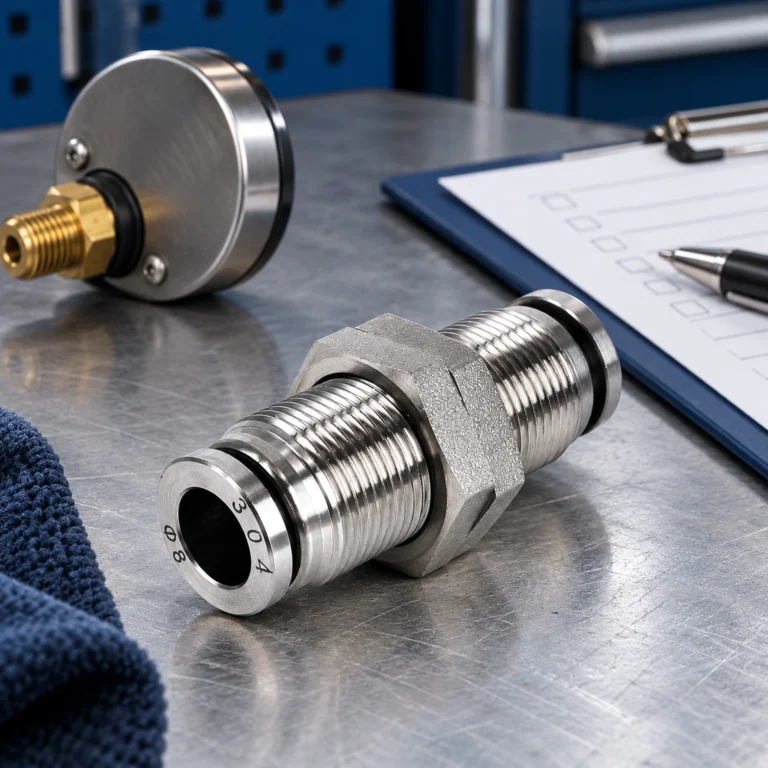
Pneumatic components convert compressed-air energy into controlled movement or switching. Typical automation equipment uses cylinders for linear motion, valves for directional control, fittings and hoses for distribution, and regulators or filters to condition the air. The practical advantage is architectural simplicity: a controller can command a valve, while the actuator performs a defined stroke without a motor, drive, and mechanical transmission at every station.
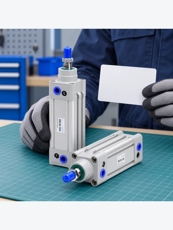
That advantage has boundaries. Compressed air is generated upstream, so the installed cost and operating impact depend on the compressor, treatment equipment, distribution network, duty cycle, and leakage. The U.S. Department of Energy’s compressed-air sourcebook recommends treating the air system as a complete system; a component-level claim about “low energy consumption” is not enough to establish plant-level performance.
How could connected sensing change pneumatic automation?
Industry 4.0 integration is most useful when a sensor answers a defined maintenance or quality question. A pressure sensor can show whether a circuit reaches its intended operating range; a switch can confirm cylinder end position; a flow or leak-monitoring device can highlight an unusual demand pattern. These signals can be mapped to a PLC or supervisory system for alarms, trend review, and maintenance work orders.
Connectivity does not make an unsuitable circuit suitable. Before adding a gateway, define the signal’s decision rule: for example, an alarm after repeated low-pressure events during a known cycle. Record the sensor location, sampling assumptions, and acceptable operating window in the machine documentation. ISO 12100:2010 is a machinery risk-assessment and risk-reduction framework; it can guide the safe treatment of faults and unexpected motion, but it does not certify a particular sensor network.
Component choice should follow the control problem. A solenoid valve explanation can help clarify directional-control terminology, while the manufacturer’s pneumatic parts range provides a starting point for checking available fittings, hoses, cylinders, and valves. Verify every rating and interface against the current product documentation.
What practical advantages can pneumatic components provide?
The defensible advantages of pneumatic products are application-dependent rather than absolute. They can deliver quick on/off motion, tolerate frequent cycling when correctly sized, and support compact machine layouts. Fittings and hoses also make changes to a prototype or service assembly relatively straightforward. These benefits are strongest when the motion is binary or has modest positioning demands and when air preparation and exhaust routing are already available.
| Decision dimension | Pneumatic approach | Electric motion approach | Engineering question |
|---|---|---|---|
| Typical motion | Discrete stroke, clamp, eject, or grip | Servo or stepper position profile | Is the required motion binary or continuously commanded? |
| Control precision | Depends on valve, sensing, pressure, and mechanics | Often suited to commanded position and speed loops | What repeatability and settling behavior are specified? |
| Infrastructure | Needs compressed-air generation and treatment | Needs electrical supply, drive, and cabling | Which utilities are already available at the machine? |
| Maintenance focus | Leakage, contamination, tube seating, seals, and pressure | Cooling, bearings, cables, drives, and mechanical transmission | Which failure modes can the team inspect and service? |
| Safe-state design | Must address stored pneumatic energy and exhaust behavior | Must address electrical and mechanical energy | What happens after loss of power or air? |
This is a selection framework, not a performance ranking. A mixed architecture is often reasonable: pneumatics for clamps or simple transfer and electric axes for controlled positioning. The correct choice follows the motion profile, risk assessment, available utilities, and total cost of ownership.
How should engineers reduce waste and unplanned stops?
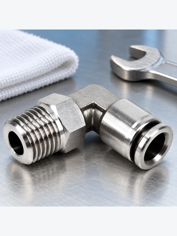
Start with a baseline. Record compressor pressure, machine inlet pressure, cycle count, and the operating state in which failures occur. Then inspect common loss points: push-in connections that are not fully seated, damaged tube ends, cracked hoses, blocked silencers, contaminated filters, and regulators set incorrectly. The DOE sourcebook treats leakage management and pressure optimization as system practices; neither should be inferred from a fitting’s marketing description.
Use a repeatable maintenance route. Mark connection points, inspect tube cuts and bend radii, and confirm that replacement parts match thread, tube, seal, temperature, and pressure requirements. Where a change affects stored energy or guarding, update the machine risk assessment and isolation procedure. A clear bill of materials and accessible spares can reduce recovery time without claiming a guaranteed percentage saving.
How should an air-saving retrofit be measured?
Define the measurement boundary before choosing a sensor or promising a saving. A flow meter at one machine measures that branch; a compressor power meter measures the electrical behavior of a wider supply system. The two quantities answer different questions. Record the baseline production rate, part mix, cycle time, supply pressure, operating hours and idle periods so the before-and-after comparison represents similar work.
For a machine-level assessment, report air use per accepted production cycle together with the required cycle time and quality result. State the flow unit and its reference conditions; standard-volume readings from one convention should not be silently mixed with actual line-volume readings or another reference basis. Account for changes in operating pressure or measurement position. A lower flow reading achieved by slowing the machine or producing fewer good parts is not evidence of a like-for-like efficiency improvement.
The U.S. Department of Energy’s Compressed Air Evaluation Protocol separates baseline and post-retrofit assessment and explains why compressor control behavior matters to electrical savings. Its Minimize Compressed Air Leaks tip sheet also advises aligning compressor operation with reduced demand. These sources support a measured comparison, not a fixed percentage saving for every retrofit. Retain the meter identity, measurement period, uncertainty information and operating record, and have an appropriate specialist review any energy claim.
Which component and integration checks matter before procurement?
Procurement teams should translate the machine requirement into a component specification rather than selecting by a catalogue photograph. Keep the decision traceable from the application to the installed part, including the evidence needed at commissioning.
| ពិនិត្យ | What to document | Why it matters at commissioning |
|---|---|---|
| Motion and load | Stroke, load direction, cycle profile, cushioning, and required repeatability | Prevents an actuator or valve from being sized only by nominal bore |
| Air conditions | Available pressure, air quality, temperature, and expected demand | Aligns filters, regulators, seals, and operating limits with the real circuit |
| Interfaces | Tube OD, thread type, port orientation, valve signal, and mounting | Reduces rework and prevents incompatible substitutions |
| Safety and isolation | Exhaust path, residual pressure, guarding, lockout, and restart behavior | Supports the risk-reduction process described by ISO 12100 and ISO 4414 |
| ផែនការផ្ទៀងផ្ទាត់ | Leak check, stroke confirmation, sensor response, and acceptance records | Creates evidence for handover and future fault finding |
For a reference on motion terminology, see the guide to how a pneumatic cylinder works. For part discovery across product families, use the products directory, then request current drawings, material information, and operating limits for the exact part under consideration.
Which sensor signals lead to a useful maintenance action?
A pressure alarm is useful only when its location, timing and response are defined. A pressure dip during acceleration may mean something different from a slow decay during a documented hold period. Similarly, increased flow could reflect a leak, an intentional process change or a faster production cycle. Relate measurements to the machine state and compare the same operation before creating a fault diagnosis.
Start with one observable failure mode, such as a recurring leak at a moving connection or a clamp that no longer reaches its expected state. Define the signal that warrants inspection, who receives the alert and what evidence the technician should collect. The pneumatic fitting maintenance guide can provide the connection-level inspection context. A monitoring dashboard without an agreed action can add data while leaving the underlying maintenance problem unresolved.
For purchasing, specify access to the readings, sensor replacement arrangements and configuration records. Check how loss of a sensor or network connection affects ordinary control and the separately designed safety functions. Predictive maintenance should be presented as an application to validate, not a guarantee that software will predict every seal failure. Evaluate connected pneumatics against electric alternatives using the same motion, utility and maintenance requirements rather than an Industry 4.0 label.
What do the relevant standards actually cover?
- ISO 4414:2010: general rules and safety requirements for pneumatic fluid-power systems and their components. It informs design and safety practices; it is not, by itself, proof that every component has a specific performance certification.
- ISO 12100:2010: general principles for machinery design, risk assessment, and risk reduction. Apply it to the machine and its hazards, including unexpected pneumatic movement and stored energy.
- DOE compressed-air sourcebook: an industry guide to improving compressed-air system performance. It is practical guidance, not a product certificate or a substitute for site measurements.
Applicability depends on the machine, destination market, installation environment, and claims made in technical or marketing documents. Ask suppliers to identify the exact standard edition, scope, test evidence, and limitations. Avoid converting a test method, design guideline, or general conformity statement into an unsupported efficiency, safety, or environmental claim.
សំណួរដែលសួរញឹកញាប់
What are pneumatic products used for in automation equipment?
They are used for functions such as clamping, gripping, ejecting, indexing, and other controlled linear or rotary actions. A valve, actuator, air-preparation device, hose, and fitting work as a circuit, so the application requirement must be checked as a system.
Are pneumatic systems still relevant to Industry 4.0 automation?
Yes, when their signals and maintenance needs are made visible through suitable sensors and controls. Connectivity supports diagnostics and trend review, but it does not remove the need for correct sizing, safe isolation, and leakage control.
How can a factory reduce compressed-air waste in an automated line?
Measure the system at representative operating states, repair leaks, confirm pressure settings, and review unnecessary blow-off or idle demand. Use the DOE sourcebook as system guidance and verify any improvement with site measurements rather than a component-level claim.
What should engineers check before replacing a pneumatic actuator?
Check stroke, load direction, cycle rate, available pressure, cushioning, mounting, ports, seals, temperature, and the required safe state. Confirm the replacement against the valve, tubing, sensors, and machine risk assessment before installation.
Which sensors are useful for monitoring pneumatic equipment?
Pressure, end-position, flow, and leak-monitoring sensors can be useful when each has a defined decision or alarm rule. Select the location, range, response, environment, and interface from the diagnostic question, not from connectivity alone.
When should an automation line use electric motion instead of pneumatics?
Electric motion is often worth evaluating when the process needs coordinated profiles, frequent position changes, or tightly controlled speed and position. Compare both options using the actual cycle, utility infrastructure, safety design, maintenance capability, and total cost of ownership.
What is the difference between air savings and electricity savings?
Air savings describe reduced demand at a defined flow-measurement boundary. Electricity savings depend additionally on compressor loading, control response and operating hours. Measure both quantities when making a claim about both.
Does lower air consumption per hour prove that a retrofit is more efficient?
No. Compare accepted production output, cycle time, pressure and operating state. A machine running more slowly may consume less per hour without improving consumption for the required production task.
ឯកសារយោង
- U.S. Department of Energy / NREL, Uniform Methods Project, Chapter 22: Compressed Air Evaluation Protocol, 2014
- U.S. Department of Energy, Minimize Compressed Air Leaks, Tip Sheet 3
Summary
Pneumatics remains useful when the required motion, available air supply and maintenance arrangements fit the application. Future improvements should be judged by measurable operating results: reliable motion, controlled air demand and faults that technicians can investigate. Define the production task and measurement boundary before adding sensors or claiming an efficiency gain. Compare air consumption at equivalent output, and check compressor behavior before converting reduced demand into an electricity-saving claim. Keep ordinary monitoring separate from the machine’s validated safety functions. Oulu’s pneumatic parts can be reviewed as components of that documented design, with the actual interfaces, operating conditions and service requirements established before procurement or replacement.