When a process engineer in Oulu traced inconsistent pick-and-place motion at an injection-molding cell, she first changed a valve setting. The gripper still hesitated, and a hiss appeared at full reach. The root cause was not a failed valve: the tube-to-elbow connection had not allowed for movement, tube material, or the fitting’s flow path. Re-specifying the interface and verifying the branch addressed the problem.
まとめ: pneumatic fittings in plastic manufacturing connect air preparation, valves, cylinders, grippers, and blow-off points; select them for the complete duty, not nominal thread size alone. ISO 6358-1 expresses pneumatic-component flow characteristics, while ISO 8573-1 classifies compressed-air contaminants. Record tube outside diameter, port thread, media, limits, motion, and exposure; then test the completed assembly for leakage and function before release.
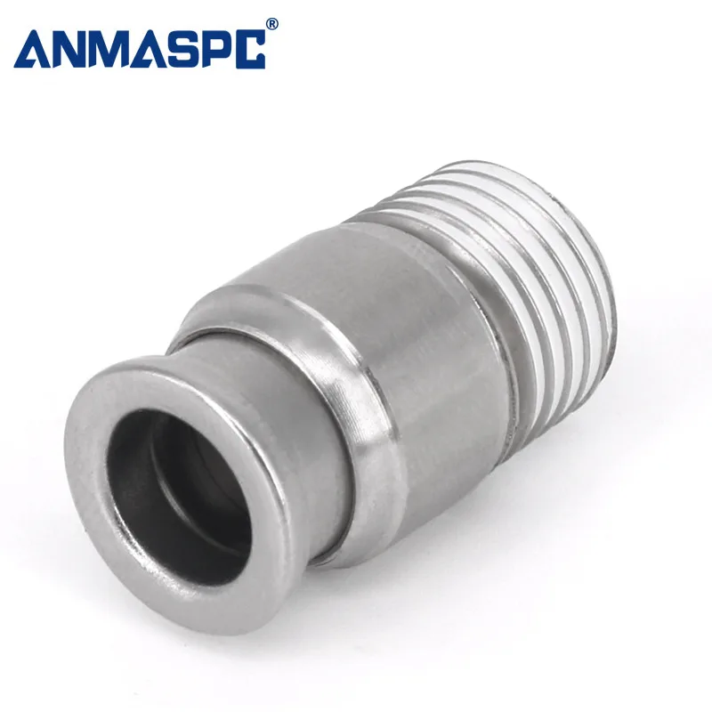
Where pneumatic fittings support plastics processing
圧縮空気 operates actuator control, robotic end effectors, conveying auxiliaries, valve islands, part ejection, and controlled blow-off. Fittings make these circuits serviceable: straight connectors extend a route, elbows manage direction changes, tees feed branches, and threaded adapters connect equipment ports. Each fitting is both a connection and part of the flow path.
For a molding-cell or extrusion-line buyer, ask whether the entire branch can supply the intended motion. ISO 6358-1 is a test method for flow-rate characteristics of pneumatic components with compressible fluids; it supports comparable data instead of an unqualified “high-flow” description. Include tube internal diameter and length, reducers, valve-port size, and actuator demand in the review.
| Plastics-manufacturing duty | Typical fitting role | Selection priority | Installation check |
|---|---|---|---|
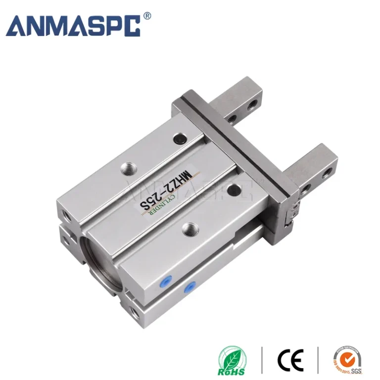
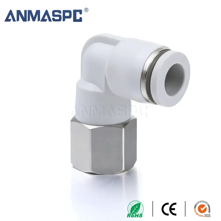
| Robot gripper or pick-and-place arm | Elbow or swivel-oriented tube connection | Tube flexing, clearance, side-load control, and flow path | Observe a full representative motion cycle |
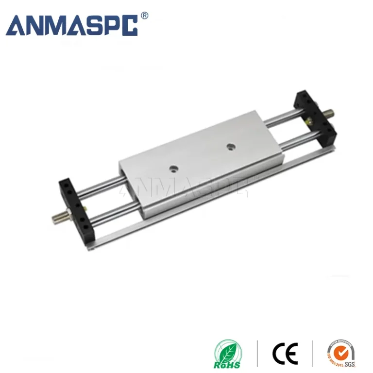
| Mold ejector or pneumatic cylinder | Threaded port adapter or straight fitting | Correct thread form, seal method, and branch capacity | Leak-test at the documented operating condition |
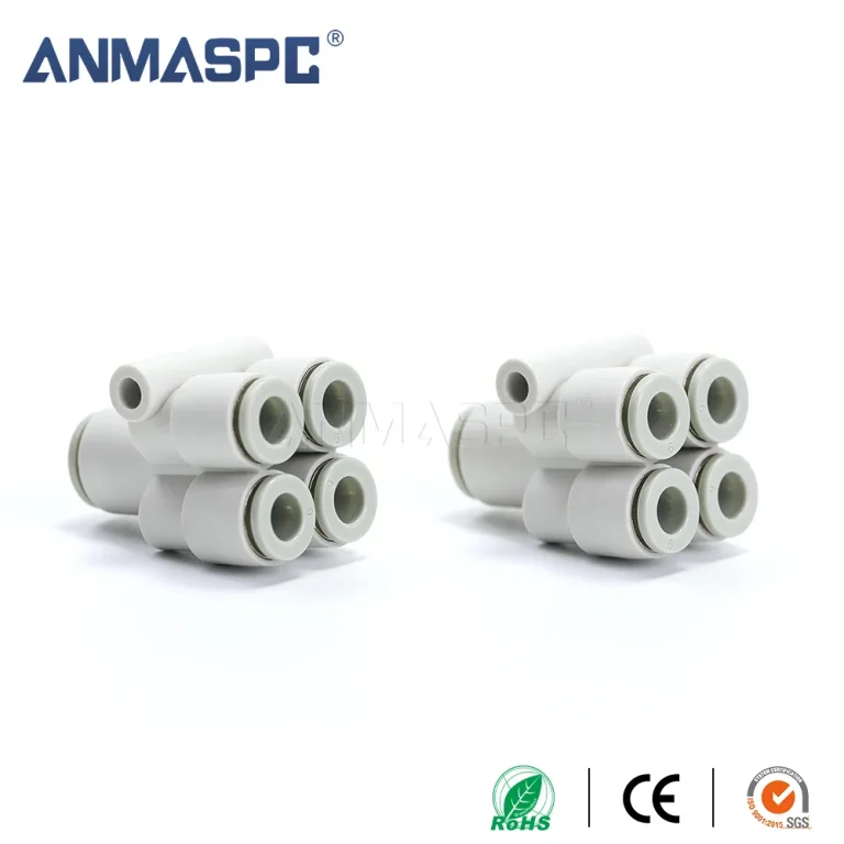
| Conveying or air-assist auxiliary | Tee, reducer, or manifold connection | Shared branch demand and accessible isolation | Check pressure change when adjacent users cycle |
| Part cooling or approved blow-off point | Tube-to-port connection | Purpose, guarding, and applicable site safety controls | Verify the nozzle and air-use practice separately |
Material, tubing, and air quality must be evaluated together
A fitting body alone does not define compatibility. Engineered-polymer, brass, and stainless-steel constructions have different considerations, while the seal and tube may be limiting components. Start with the compressed-air condition, lubricant carryover, moisture, cleaning agent, heat, and contact time. Ask for model-specific material and seal guidance rather than inferring chemical resistance from a generic material name.
Tube selection matters equally at a push-in connection. Polyurethane tubing can offer routing flexibility, whereas polyamide tubing provides a different stiffness balance. Buyers comparing PU and PA air hose should confirm the approved tube range, outside-diameter tolerance, bend radius, and installation condition. ISO 8573-1 classifies particles, water, and oil in compressed air; it is not a fitting-material certificate.
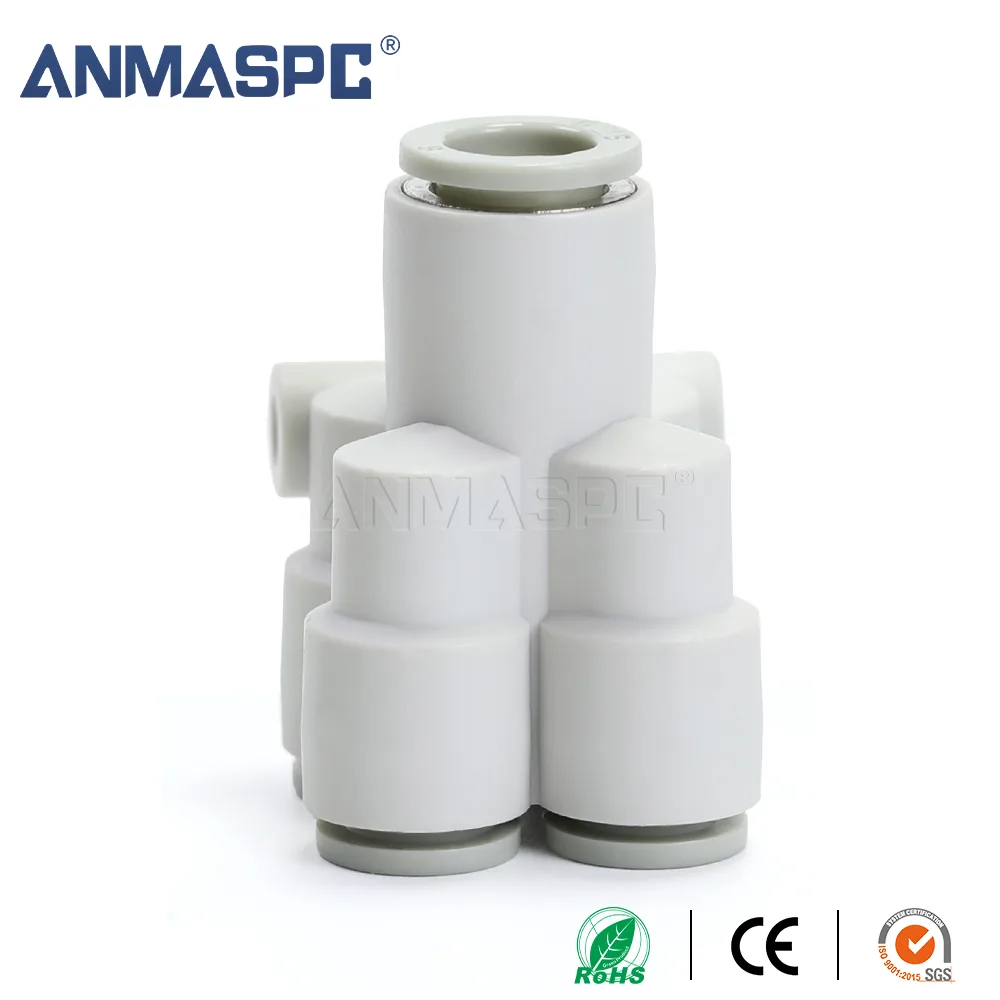
| Condition to document | Information required from the application | Procurement implication |
|---|---|---|
| チューブインターフェース | Tube OD, material, hardness, bend radius, and movement | Confirms gripping, sealing, and routing suitability |
| ポートインターフェース | Thread designation, size, gender, and sealing geometry | Avoids joining similar-looking but incompatible threads |
| Process exposure | Temperature range, oils, cleaners, moisture, dust, and contact duration | Determines the required body and seal compatibility review |
| Air and flow demand | Air-quality requirement, supply condition, tube ID and length, duty cycle | Supports a whole-branch flow and maintenance assessment |
| Service access | Isolation point, release-ring clearance, inspection access, replacement route | Reduces avoidable disruption during planned maintenance |
Leak control and system safety are production considerations
A compressed-air leak can increase compressor demand and may change local actuator behavior; its effect depends on leak size, storage, regulation, line capacity, and the motion being controlled. Treat it as an engineering finding, not proof that a fitting alone is defective. Inspect tube cuts, insertion depth, damaged tube, pull load, thread seal method, vibration, and port condition before replacing components.
ISO 4414 sets general pneumatic-system safety requirements; it is not blanket certification for an individual fitting. In the United States, OSHA 29 CFR 1910.242(b) limits compressed air used for cleaning to 30 psi or less with effective chip guarding and personal protective equipment. That rule does not establish automation-circuit pressure. Requirements depend on destination market, intended use, equipment risk assessment, and finished-system claims.
A practical selection and maintenance routine
- Map each air branch from preparation unit to end device, including tube sizes, thread forms, reducers, valves, and moving sections.
- Specify normal and maximum pressure, temperature, media, air-quality requirement, process exposure, and required documentation for the exact part.
- Select the configuration that preserves routing clearance and avoids tight bends or unnecessary adapters. For common tube-end designs, compare the operating requirements with ワンタッチ fitting selection guidance.
- Cut tubing squarely, follow the manufacturer’s insertion and sealing instructions, then test the completed branch under representative controlled conditions.
- Maintain an approved pairing list for tube and fitting part numbers; inspect moving routes, fittings near heat sources, and connections exposed to cleaning chemicals on the site’s planned schedule.
Unit price is only one buying input. Extra adapters, poor access, or missing technical data can add engineering and maintenance work. OULU can support an application-led inquiry for pneumatic straight fittings and related connections when a drawing, tube specification, and service conditions are available.
よくある質問
Why are pneumatic fittings used in plastic manufacturing?
They connect compressed-air tubing to valves, actuators, grippers, manifolds, and process auxiliaries, while enabling branches and direction changes. Their suitability depends on the whole circuit—particularly interfaces, flow demand, movement, and exposure. Document those conditions before selecting a geometry.
What pneumatic fitting materials suit plastic processing plants?
Engineered polymers, brass, and stainless steel can each be considered, but no body material is universally suitable. Evaluate the fitting body, seal, and tube against heat, oils, cleaners, moisture, and the actual compressed-air condition. Obtain compatibility guidance for the exact model and exposure.
How do I choose fittings for robotic pick-and-place lines?
Start with motion range, tube bend radius, routing clearance, actuator flow need, and the port interface. Position elbows and supports to limit side load, and ensure release rings remain accessible. Run the intended motion cycle and inspect the connection before standardizing it.
Can compressed air leaks affect plastics production?
They can add air demand and, depending on circuit capacity and timing, contribute to inconsistent local pneumatic behavior. Diagnose the entire branch, including tubing, port sealing, and moving loads, rather than attributing every symptom to a fitting. A controlled leak and function check provides evidence for the repair decision.
How do heat and chemicals affect pneumatic tubing and fittings?
They may change material behavior or seal performance, and the result depends on chemical identity, concentration, temperature, duration, and mechanical stress. Cleaner overspray and radiant heat deserve the same review as the conveyed medium. Use current supplier documentation for the assembled tube, seal, and fitting combination.
What maintenance checks reduce unplanned downtime?
Use planned checks for damage, tube cuts, insertion depth, side load, vibration, abrasion, leakage, and restricted access. Review moving routes through a representative cycle and keep approved replacements tied to documented tube and fitting pairings. Escalate recurring findings to the equipment owner for a root-cause review.
参考文献
- ISO 6358-1: Pneumatic fluid power — Determination of flow-rate characteristics of components using compressible fluids.
- ISO 4414: Pneumatic fluid power — General rules and safety requirements for systems and their components.
- ISO 8573-1: Compressed air — Contaminants and purity classes.
- U.S. OSHA, 29 CFR 1910.242: Hand and portable powered tools and equipment.
The dependable fitting choice is the one that matches the real interface and duty—not the one that merely resembles the old part. When a plastics-production project needs a documented connection review, explore OULU pneumatic parts and contact the team with the tube, port, operating conditions, and application drawing.