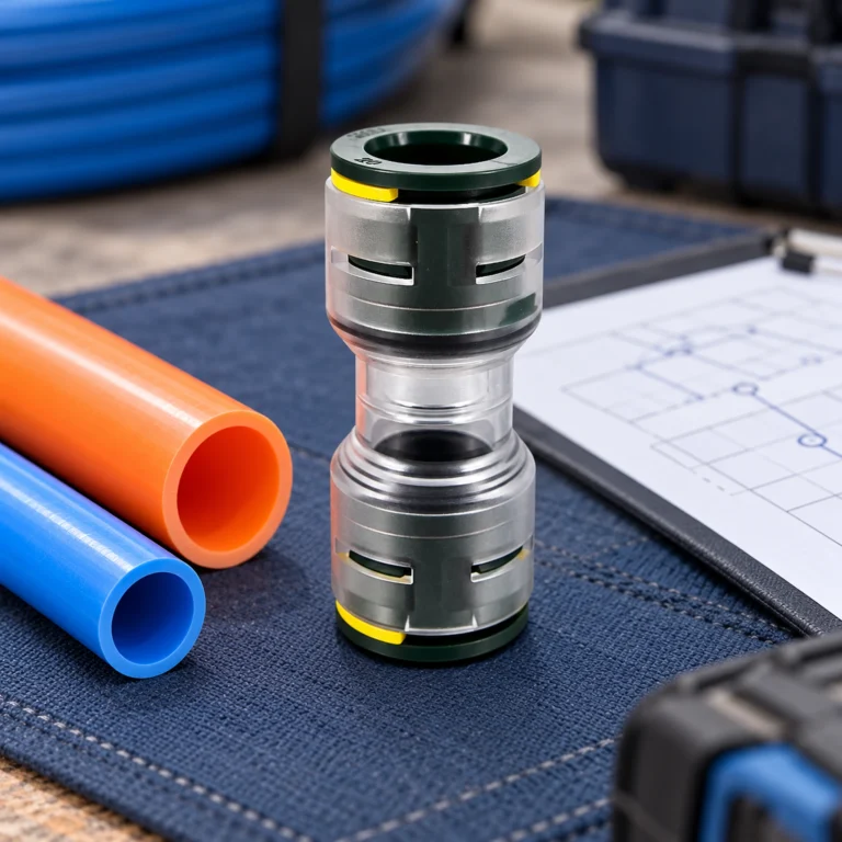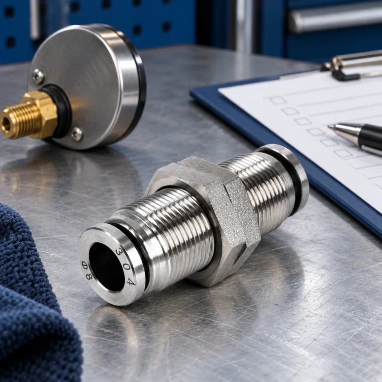
A pneumatic straight fitting can leak at the tube entry, threaded port, body or adjacent tubing. Those faults can sound similar while requiring different repairs. Locate the actual interface first, then inspect the tube, thread, seal and support under the plant’s isolation and testing procedure. Replacing the connector without finding the cause often leaves a recurring fault.
Common fitting faults involve tube preparation, pressure and temperature, thread treatment or material compatibility. Inspect these conditions alongside the fitting itself. ISO 4414 frames pneumatic systems around safe design and operation, while ISO 8573-1 classifies compressed-air contaminants; use them alongside the supplier instructions to check tube OD, cut quality, thread interface, and air quality before replacing parts. Start with a controlled isolation and leak test, then correct the cause rather than repeatedly tightening the joint.
Pneumatic straight fittings join tubing or threaded ports in a direct line. Their reliability depends on the complete interface through installation, vibration, and service—not on the connector alone.
Why a straight fitting starts to leak
Tube-end defects and incomplete engagement. In a push-in connection, the collet holds the tube and an internal seal closes around its outside diameter. An angled, burred, scratched, painted, or out-of-round tube can defeat either function. Make a square, clean cut and insert fully to the stated stop; after rework, do not shorten the tube into a damaged section.
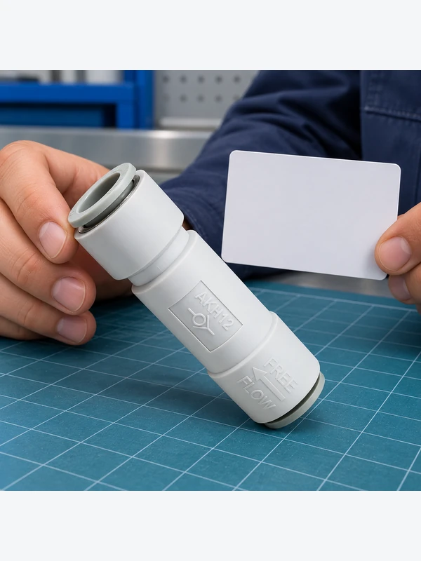
Thread, seal, and torque errors. BSPP, BSPT, NPT, and metric threads are not interchangeable because they look similar. Some use a face seal or bonded washer; tapered threads need controlled engagement and the approved sealing method. Cross-threading, excess tape, and overtightening can damage a port. ISO 4414 is a system-safety standard, not a fitting certification.
Duty conditions beyond the specification. Pressure spikes, heat, vibration, washdown, lubricants, and contaminated air change risk. A nominal 6 bar line is about 600 kPa, but selection must use the actual maximum pressure and transient conditions. ISO 8573-1 classifies particulate, water, and oil contamination; it does not certify a connector for every chemical.
Check the tube, thread, and seal before replacing parts
Follow the plant isolation procedure, exhaust stored energy, then inspect the fitting, tube, port, and supports. OSHA cautions that compressed air can cause serious injury. Restore pressure in a controlled manner and use the site-approved leak-detection method. Bubble solution is useful locally; higher-consequence applications should use the equipment maker’s defined pressure-decay test and record pressure and duration.
Air leakage is often audible, but a hiss does not prove the connector is the source. After safe depressurization, inspect seating, the witness mark, seal, and tube end. Replace cracked parts; if the leak returns after a cycle, investigate tube movement, bend radius, side load, and vibration support.
| Síntoma observado | Likely mechanism | Useful check | Acción correctiva |
|---|---|---|---|
| Hiss at tube entry | Damaged, undersized, or incompletely inserted tube | Inspect square cut and insertion witness mark | Recut or replace tube; insert to the specified stop |
| Fugas en el puerto roscado | Wrong thread family, seal method, or torque | Verify port and fitting thread specification | Use the specified mating part and sealing approach |
| Tube ejects under load | Tube OD/tolerance or collet engagement problem | Comprobar tube material, OD, and retention after isolation | Replace incompatible parts; remove side load |
| Slow actuator or pressure loss | Leak, restriction, or contaminated supply | Compare pressure at supply and point of use | Locate loss and review filtration and line sizing |
Locate tube-entry and port-thread leaks separately
Mark the suspected joint and distinguish the two interfaces before disassembly. A push-in tube entry seals against the tube’s outside surface; a threaded adapter has a separate port interface whose sealing arrangement depends on its design. The location of a hiss alone is unreliable because air can travel along surrounding surfaces. Use the site-approved leak-detection method to identify where leakage first appears, under controlled test conditions and with access kept outside moving or stored-energy hazards.
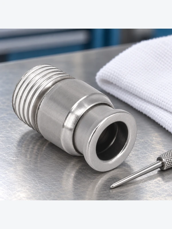
Isolate the equipment and release stored pressure before touching, loosening or removing the assembly. Inspect the tube sealing zone for scoring, an angled cut, ovality and damage from a previous collet. Verify tube OD and material from markings or the controlled specification rather than colour. Confirm the fitting’s insertion instructions and release method. The one-touch fitting guide gives background on the gripping and sealing interface, while the actual supplier instructions determine the permitted tube combination.
Inspect the port separately. Record the complete thread designation and how the joint is intended to seal: on the thread, against a face, or through a specified gasket or O-ring. A fitting that starts to screw into a port is not proof of compatibility. Avoid adding sealant to a tube entry or compensating for damaged threads with extra tape. Replacement and assembly torque must follow the exact product and port instructions.
After the approved correction, perform a controlled retest. Keep the local leakage result separate from a pressure-drop observation across the whole circuit; a restriction elsewhere can still slow an actuator after the joint is repaired. Record the fitting code, tube identity, observed leak location, corrective action and test conditions. This turns a repeated “bad fitting” complaint into a fault history that engineering can compare across machines.
Choose the connection for the service conditions
Push-to-connect fittings can reduce assembly time when the specified tube and duty conditions are respected. Threaded adapters may better suit a fixed port interface. Include rework, leak testing, downtime and possible port damage in the cost comparison.
| Selection dimension | Push-in straight connector | Threaded straight adapter | Implicación de contratación |
|---|---|---|---|
| Installation speed | Fast when tube is square-cut and fully seated | Requires controlled thread engagement | Compare installed labor, not only purchase price |
| Primary compatibility control | Tube OD, material, tolerance, and pressure | Thread family, seal type, port material, and torque | Specify both sides of the interface on the PO |
| Maintenance exposure | Tube can be replaced without turning the body | Repeated disassembly can affect threads or seals | Plan a documented inspection/replacement method |
| Total-cost driver | Cut quality and avoidance of tube damage | Correct sealing and avoidance of port damage | Track repeat leak calls and machine downtime |
For example, a connector that costs slightly more but avoids one repeat call-out can lower total cost when the avoided labor, lost output, and re-test time exceed the price difference. This is not a universal saving claim; the result depends on labor rates, machine criticality, and the documented failure rate at the site.
Reproduce a movement-related fault without handling a live joint
A connection that seals at rest but leaks during a machine cycle needs a test that represents that cycle. First review tube routing in the safely isolated state: check whether travel pulls the tube sideways, whether the bend tightens at one end of motion, and whether a support transfers force into the connector. A stronger fitting will not necessarily correct a short tube, an unsuitable bend or a moving assembly that requires a different connection design.
Agree a controlled test with the responsible maintenance and safety personnel. Record the machine position, authorised operating cycle, supply conditions and point where the symptom occurs. Observe through the normal safeguards or appropriate remote instrumentation; never reproduce the fault by pushing, bending or tightening a pressurised joint by hand. If the test cannot be performed with the required guarding and access controls, revise the procedure before continuing.
Compare the rest condition and movement condition at the same identified measurement points. Note pressure at the supply and point of use, the timing of the leak, actuator demand and any temperature change. Do not label ordinary cycle-related pressure change as a quantified leakage rate without the necessary measurement method. The Guía de mantenimiento can support the inspection plan, but it does not establish a universal pass pressure, test duration or number of cycles.
The U.S. Department of Energy’s leak-management guidance treats detection, repair and follow-up as a continuing process. After each repair, verify the result, tag unresolved faults and check whether leakage returns at the same location. Calculate any energy saving from measured operating hours and site data rather than attaching a generic percentage to a new connector. Check the Ámbito de piezas neumáticas only after the interface and duty requirements have been defined.
Follow isolation rules and check the fitting’s operating limits
Use standards precisely. ISO 4414 addresses safety requirements for compressed air systems and components. ISO 8573-1 establishes compressed-air purity classes. ISO 12100 addresses machine risk assessment and reduction. None by itself proves a fitting is approved for food contact, potable water, explosive atmospheres, or every market.
Ask for rated media, pressure and temperature range, compatible tube materials, thread standard, and test documentation. A pressure-decay test is a method or acceptance procedure unless its governing standard and scope are stated. Unsupported compliance claims create commercial risk.
What to record after a repair
- Define the port thread, seal, tube OD/material, pressure, temperature, media, and exposure on the purchase order.
- Standardize tube cutting and insertion checks; avoid tool damage and side load.
- Set an ISO 8573-1 air-quality target where appropriate and align filtration to duty.
- Record repeat faults; inspect supports, bend radius, and machine vibration before replacing parts again.
- Request dimensional and application documentation for critical lines. ANMASPC / Microduct Connector can help buyers review configurable product options and documentation before a production change; for an application discussion, use the contact team.
Preguntas frecuentes
Why do pneumatic straight fittings leak?
Common causes are a rough or angled tube cut, incomplete insertion, wrong tube OD, damaged sealing surfaces, incompatible threads, or duty outside the specified pressure and temperature range. Isolate the line, inspect the full interface, and test after the correction; do not assume the visible fitting body is the source.
How do you stop an air fitting from leaking?
Identify whether the leak is at the tube entry, thread, body, or adjacent tube before changing parts. Use the fitting maker’s specified tube and thread method, prepare the tube cleanly, and confirm the joint with a controlled leak check at the intended operating conditions.
What causes a push-to-connect fitting to fail?
A push-in fitting may lose retention or sealing when the tube is incompatible, out of tolerance, scratched, poorly cut, or subjected to excessive side load. Contamination, heat, chemical exposure, or installation beyond the stated pressure range can also affect performance; check the product documentation and the system conditions together.
Can pneumatic fittings be reused?
Reuse depends on the manufacturer’s instructions and the condition of the fitting, seal, tube, and threads. Do not reuse a component with a cracked body, damaged collet, distorted seal, compromised thread, or unknown service history; for critical service, replacement and documented testing are usually the safer maintenance choice.
How tight should pneumatic fittings be?
Threaded fittings should be tightened to the manufacturer’s torque or assembly guidance for the exact thread, port material, and sealing arrangement. Push-in tube connections are not tightened by torque: insert the prepared tube fully to the stop and verify retention in accordance with the supplier’s procedure.
What tubing works best with pneumatic straight fittings?
The best tubing is the material and exact outside diameter that the fitting manufacturer lists for the pressure, temperature, bend radius, and media in the application. Polyamide, polyurethane, polyethylene, and fluoropolymer tubing each have different flexibility and chemical/thermal characteristics, so specify from documentation rather than selecting by appearance.
Does ISO 4414 specify the pressure rating of every straight fitting?
No. ISO 4414 gives general rules and safety requirements for pneumatic systems and components. The exact fitting datasheet still controls the approved pressure, temperature, medium and installation limits.
What evidence should a buyer request after a recurring fitting leak?
Request the fitting code, tube OD and material, thread standard, seal specification, operating conditions, failure location, corrective action and the retest record. That evidence is more useful than a generic claim that the fitting is high pressure.
Why can a fitting seal when stationary but leak while the machine moves?
Tube movement can impose side load, tighten a bend or disturb a damaged sealing zone. Inspect the route while safely isolated and reproduce only the authorised operating cycle with safeguards in place. A static pass does not demonstrate satisfactory behaviour during movement; record the cycle condition and location of the fault.
Should thread tape be added to stop a leak at the tube entry?
No. Thread sealant is not a repair for the tube-to-seal interface. Identify tube size, insertion, surface condition and compatibility, then follow the manufacturer’s repair instructions. A threaded port may require its own specified sealing method, but the two interfaces should be diagnosed separately.
Referencias
- SMC — KQ/KQ2 one-touch fittings catalogue (series-specific tube and assembly data)
- U.S. Department of Energy — Improving Compressed Air System Performance: Minimize Compressed Air Leaks
- ASME B1.20.1 — Pipe Threads, General Purpose (Inch), official scope
Resumen
Locate the leak at the tube entry or threaded port before deciding how to repair the fitting. Separate the tube entry from the threaded port, isolate stored energy before intervention and inspect the complete tube-and-fitting combination. Correct the root cause, then verify the result under the authorised conditions that produced the fault. Where leakage appears during movement, check routing and support and use a safeguarded operating-cycle test rather than manipulating a live connection. Retain the part identities, leak location and before-and-after observations. Those records make repeated faults easier to investigate and help distinguish a connector defect from tube damage, incompatible threads, restricted flow or mechanical loading.