
When Maya, a fiber-installation supervisor in an illustrative Rotterdam scenario, encountered a leaking joint, she re-cut the HDPE duct and pushed it into a connector marked for the job. The pressure gauge still dropped within a minute. A caliper check reversed the diagnosis: the connector was not automatically “bad”; the purchasing file had mixed nominal duct language, measured outside diameter, and the wrong connection type.
Summary: Choose a Dura-Line Microduct 12.7mm Connector from verified duct dimensions, not a “close enough” label. Dura-Line lists its 12.7 mm straight coupler for 12.7 mm OD/10 mm ID microduct and publishes a 232 psi/16 bar use rating for the coupler range.[1][2] Measure the duct OD, confirm the exact part drawing, prepare a square undamaged end, and pressure-test the assembled route to an approved project method and hold time.
Trademark note: Dura-Line is a third-party brand. This independent selection guide does not claim affiliation, approval, identical construction, interchangeability, equivalence, or replacement status for any other supplier’s products.
Why the 12.7 mm Label Does Not Confirm Fit
The official Dura-Line listing identifies part 20001832 as a 12.7/10 mm OD/ID straight coupler and lists separate transition couplers for unequal diameters.[1][2] That matters because 12 mm, 12.7 mm, and 14 mm are different interfaces even if a crew informally calls them “half-inch” duct.
The Micro duct belongs to a blowing system. ITU-T L.108 covers characteristics and tests for blown microduct fiber units and cables, while IEC 60794-5-20:2014 covers outdoor microduct units, microducts, and protected microducts.[3][4] Neither standard makes an unspecified connector a certified match. This sizing and air-leak guide explains the broader failure mechanism.
Use Outside Diameter to Match the Connector and Inside Diameter to Check the Air Path
Measure actual OD with a calibrated caliper at several points and orientations. In Dura-Line’s listing, 12.7 mm is the outside diameter that governs the interface; 10 mm is the inside bore.[1] Do not choose from ID alone or convert an inch label without the controlled drawing.
Record ovality, surface damage, wall tolerance, and whether the joint is straight or transitional. ITU-T L.108 also emphasizes dimensional control and low-friction internal surfaces for blowing.[3] Approval therefore requires both a correct outside grip and a smooth joined bore.
Prepare the HDPE Ends Before Fitting the Coupler
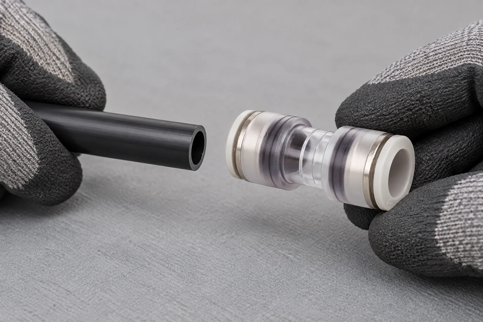
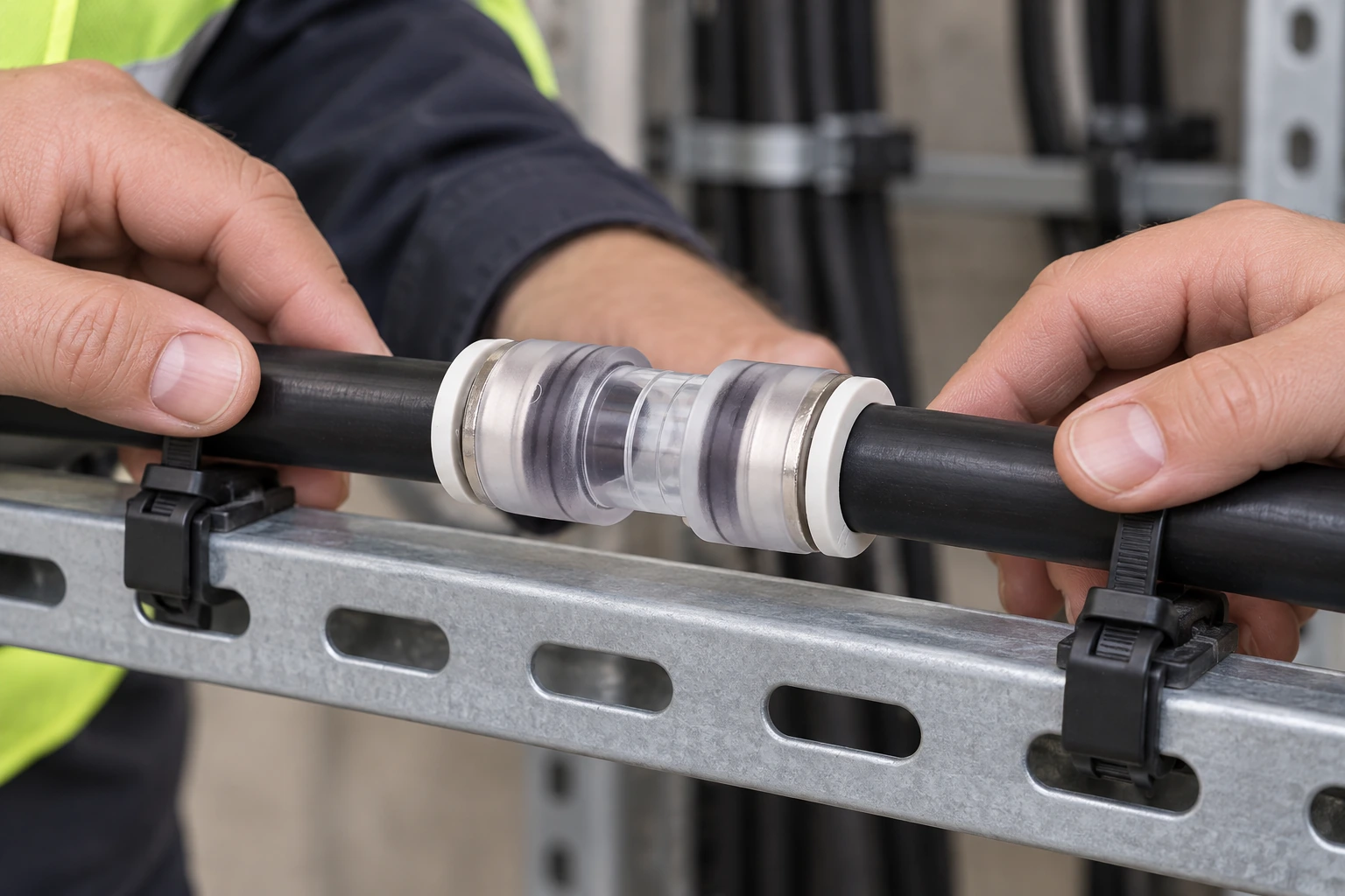
Cut each HDPE end square; remove chips, water, residue, and sharp edges; and check roundness and scoring. Insert both ends to the specified stop and fit any required locking clip. Dura-Line describes tool-free assembly/disassembly, but that does not create a universal insertion depth.[1][2] A transparent body can confirm position, not sealing.
Do not scrape, stretch, or lubricate an O-ring unless the manufacturer permits it. Inspect the body, grip, and seal for damage or contamination. Re-cut the Microduct Tube when a previous grip mark or damage reaches the sealing zone.
Find the Source of Air Loss Before Replacing the Coupler
A leak releases pressure before useful air reaches the cable, causing shorter blowing distance or repeated stops. ITU-T L.108 supplies system context, not connector approval.[3] See this air-blown microfiber installation overview.
Dura-Line publishes 232 psi/16 bar for its micro-coupler range.[1][2] This is a manufacturer limit, not an automatic field-test pressure; the lowest-rated route component controls. Illustrative cost: six joints at 20 minutes of isolation and rework consume two crew-hours, excluding remobilization. Documented sizing and testing can therefore outweigh a small unit-price saving.
Check UV and Temperature Evidence for Outdoor Use
Outdoor suitability cannot be inferred from color or transparency. IEC 60794-5-20:2014 covers outdoor microduct-system elements, and ITU-T L.108 addresses environmental tests including temperature and UV-related methods.[3][4] These do not certify every connector. The cited Dura-Line pages give no numeric temperature range or 12.7 mm-specific UV result, so request a current part-specific report with method, conditions, and acceptance criteria.
Compare Couplers by Size, Function, and Supporting Evidence
| Option | When to consider it | Approval evidence | TCO implication |
|---|---|---|---|
| Dura-Line 12.7/10 mm straight coupler | Both ends match the documented OD | Current drawing, part data, and project limits | May reduce approval and rework uncertainty |
| Documented third-party 12.7 mm straight connector | Buyer verifies fit and environment independently | Drawing, tolerance, pressure, material, UV, and temperature data | Include testing, rejects, and downtime |
| Documented transition connector | Verified duct ODs differ | Both end dimensions and bore transition | Can avoid duct replacement if approved |
| Unspecified generic fitting | No approval case without data | Resolve missing evidence before use | Low price may be offset by rework |
The rows are procurement categories, not declarations of equivalence. A third-party connector should be evaluated on its own documentation and sample results; a matching nominal size alone does not establish interchangeability with Dura-Line.
Use Leak and Seating Checks to Guide Maintenance
| Observed signal | Likely specification or process issue | Next controlled check | Commercial consequence if ignored |
|---|---|---|---|
| Pressure falls immediately | Wrong OD, incomplete insertion, damaged seal, or another open route point | Isolate sections; verify part number, OD, insertion, valves, and end caps | Repeated blowing attempts and crew delay |
| Duct pulls out | Grip range, duct surface, locking step, or axial-load requirement is unresolved | Stop testing and compare the assembly with the approved drawing and procedure | Route failure, rework, and possible cable damage |
| Visible gap through a clear body | End not fully inserted or cut not square | Depressurize, release correctly, re-cut, clean, and reinstall | Failed inspection and leak investigation |
| Leak appears only in cold or hot conditions | Temperature range or material compatibility is not demonstrated | Request part-specific cycling evidence for the destination conditions | Seasonal callouts and warranty disputes |
| Outdoor body degrades | UV exposure class or installation protection was not specified | Review test method, duration, acceptance criteria, and enclosure/shielding plan | Premature replacement and schedule risk |
Match Each Standard to the Claim It Supports
- Dura-Line documentation: the official micro-coupler page and December 2025 specification sheet identify the 12.7/10 mm straight coupler, state 232 psi/16 bar approved use, and state testing to meet or exceed CENELEC EN 50411-2-8:2009.[1][2] These are manufacturer statements; buyers should obtain current documents for the ordered part and destination.
- EN 50411-2-8: Dura-Line describes this as the standard for microduct connectors used with air-blown optical fibers.[1] Quote the edition and tested configuration rather than saying “EN approved” without a report.
- ITU-T L.108: this recommendation covers use, characteristics, and tests for microduct fiber units and microduct cables installed by blowing.[3] It informs system design and testing but is not, by itself, a connector product certificate.
- IEC 60794-5-20:2014: this family specification covers outdoor microduct fiber units, microducts, and protected microducts for blowing installation.[4] Its presence in a project specification does not prove a coupler’s pressure, UV, or temperature performance.
Unsupported compatibility, certification, UV, or temperature claims can lead to a rejected submittal, failed incoming inspection, field rework, or a warranty dispute. Applicability depends on the destination market, route environment, intended use, contract language, and the exact claims placed on the product or packaging.
Write the Purchase Specification Before Requesting Samples
- Send the controlled duct drawing, nominal OD/ID, OD tolerance, ovality limit, material, and representative production samples.
- Define the route: indoor, ducted outdoor, direct buried, aerial/lashed, chamber, or exposed cabinet; include the actual temperature and UV conditions.
- Set the test plan from the lowest-rated route component. Name the gauge accuracy, stabilization period, pressure, hold time, allowable loss, sample size, and safe depressurization sequence.
- Request part-specific drawings and evidence for pressure, pull-out, water sealing, materials, temperature, UV exposure, and any claimed standard. Check that the report revision and model scope match the purchase order.
- Define maintenance and reuse rules. Specify how gripping parts and O-rings are inspected, when seals or the full connector must be discarded, and which cleaning agents or lubricants are permitted.
For buyers assessing configurable sourcing options, Oulu / ANMASPC can review buyer-supplied drawings and requirements against its micro duct block connector and transparent-inspection straight connector product families. This is an invitation to compare specifications and evidence; it is not a claim that those products are Dura-Line products, approved replacements, interchangeable, or equivalent.
Frequently asked questions
Where can installers use the Dura-Line Microduct 12.7mm Connector in fiber and telecom networks?
Use it only where the route design, duct dimensions, environment, and approved bill of materials identify the applicable 12.7/10 mm straight coupler. Potential locations may include protected telecom duct routes and access chambers, but outdoor exposure, burial, aerial use, or enclosure installation must be supported by current manufacturer and project documentation.
How do you choose the correct duct diameter for the Dura-Line Microduct 12.7mm Connector?
Match the measured duct outside diameter and its tolerance to the exact connector drawing; Dura-Line lists part 20001832 for 12.7 mm OD/10 mm ID microduct.[1][2] Confirm ID separately for cable clearance and blowing design, and use a documented transition connector when the two duct ODs differ.
How do you install the Dura-Line Microduct 12.7mm Connector without causing an air leak?
Depressurize the route, cut each HDPE end square, remove contamination and burrs, verify roundness, and insert each end to the manufacturer’s stop before applying the specified lock. Inspect positioning where the body permits it, then test the isolated assembly under the approved project procedure.
What pressure and time should be used to test the Dura-Line Microduct 12.7mm Connector?
Use the pressure and hold time in the approved project method, never a value inferred solely from the connector maximum. Dura-Line publishes 232 psi/16 bar for its micro-coupler range, but the cited pages do not provide a universal field hold time; the lowest-rated component and safe working procedure control.[1][2]
Can the Dura-Line Microduct 12.7mm Connector be reused after the duct is disconnected?
Do not assume unrestricted reuse. Dura-Line states that its micro-couplers allow assembly and disassembly without tools, but disassembly is not blanket authorization to reuse a connector after every service condition.[1][2] Follow the current instructions, inspect the body, grip, and seal, prepare a fresh duct end, and replace any questionable component.
Which material and UV rating are best for outdoor Dura-Line Microduct 12.7mm Connector applications?
There is no universal “best” material or UV rating without the exposure, service temperature, chemicals, and design life. The cited Dura-Line sources do not state a numeric temperature range or a 12.7 mm-specific UV result, so request part-specific material and test evidence and compare it with the route conditions and applicable outdoor-system requirements.
Key Checks for a 12.7 mm Microduct Coupler
The 12.7/10 mm designation is useful only after the duct drawing, measured tolerances and route conditions are checked against the exact coupler. Keep Dura-Line’s published 16 bar figure tied to its own product evidence, distinguish a straight coupler from a transition model, and request separate documentation for temperature, UV exposure, maintenance and reuse. The 12 mm specification guide shows the same dimension-first discipline, while the air-blown installation sequence explains how preparation and testing carry that decision into the field.
References
- Dura-Line, “Micro Couplers” product page.
- Dura-Line, “MicroTechnology Accessories: Straight Couplers and Transition Couplers,” specification sheet, 12.25.
- ITU-T Recommendation L.108, “Optical fibre cable elements for microduct blowing-installation application”.
- IEC 60794-5-20:2014, “Optical fibre cables – Part 5-20: Family specification – Outdoor microduct fibre units, microducts and protected microducts for installation by blowing”.
The decision comes down to four checks: confirm the 12.7/10 mm interface, keep Dura-Line’s published figures tied to Dura-Line evidence, distinguish a straight coupler from a transition coupler, and require current documentation for the route environment and test method. A similarly sized connector should be treated as a separate product until its own drawing and records support the proposed use. That discipline is what prevents a nominal match from becoming an air-loss problem in the field.


