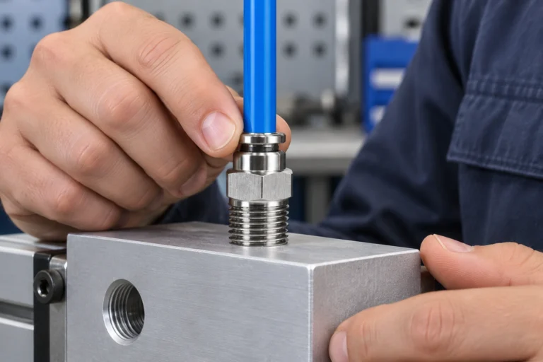
When a maintenance technician finds a hissing straight connector on an automated air line, tightening the fitting is an understandable first move. It is also why the same leak can return at the next shift change. A straight fitting may be sound while the tube OD, thread form, cut, insertion depth, seal, routing or replacement part is wrong. The visible symptom is air loss; the root cause is often an undocumented interface mismatch. This guide uses six checks to separate a thread or seal problem from a tube-preparation, retention or compatibility problem, so a team can repair the connection and leave a traceable reason for the choice.
Summary: A leaking Pneumatic Straight Fittings connection should be isolated and depressurized before inspection, then checked in this order: threaded seal, tube cut, tube seating, tube outside diameter, vibration and retention, and part compatibility. ISO 4414:2010 provides general pneumatic-system safety requirements; it does not make every fitting interchangeable. BSPP, BSPT and NPT also belong to different thread systems, so appearance is not proof of a seal. Record the actual tube and port details, compare the fitting datasheet, correct the cause, and verify the repaired joint under the approved leak-check procedure.
Which six checks usually explain a leaking straight fitting?
| Check | Evidence to inspect | Corrective action |
|---|---|---|
| 1. Thread and seal | Thread designation, size, taper, sealant condition and port damage | Confirm the thread standard and use the documented sealing method; replace damaged parts |
| 2. Tube cut | Square end, clean surface, no scoring, crushing or burrs | Depressurize, cut back to sound tubing with the approved tool and remove debris |
| 3. Tube seating | Full insertion, stable collet and no visible gap at the entry | Reinsert a sound tube to the specified depth and perform the permitted retention check |
| 4. Tube OD | Measured outside diameter, metric or inch series, and approved tube material | Match the measured OD and tube series to the exact fitting variant |
| 5. Vibration and routing | Side-load, bend close to the fitting, unsupported span and repeated movement | Support and reroute the tube; do not rely on a clip to correct wrong sizing |
| 6. Compatibility | Body, seal, medium, pressure, temperature and flow documentation | Use a documented tube-fitting-port combination and request current data for replacements |
Could the threaded side be leaking even when the fitting feels tight?
A Pneumatic Straight Fittings connection can feel tight while the thread is wrong for the port. BSPP is a parallel-thread designation commonly associated with ISO 228-1, while BSPT is used with the pressure-tight thread system in ISO 7-1. NPT is an inch-based tapered thread family covered by ASME B1.20.1. Similar diameter or partial engagement does not establish interchangeability. A forced near match can damage the port or leave a helical leak path that becomes obvious only when the line cycles.
With the system isolated and depressurized, read the port drawing or marking before removing the old fitting. Use a suitable thread gauge and measure major diameter and pitch; check taper where relevant. Remove old sealant from accessible threads without scratching the sealing surface. Reassemble only with the sealant, washer or other method specified for that thread and fitting. Do not add more torque as a substitute for thread identification, and do not treat a thread standard as a product certification.
Is the tube end cut and seated correctly?
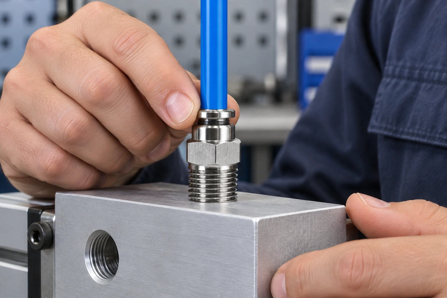
The tube-side seal depends on a clean, square end and a continuous surface. A diagonal cut, burr, scratch, flattened section or contamination can give the collet enough grip to hold briefly while the O-ring leaks. A tube that stops short of the internal shoulder can create the same symptom. Push-in action is not evidence of full seating.
After isolation, cut back to undamaged tubing with a tool intended for that tube type. Keep the new end free of chips, insert it straight and to the documented depth, and check that the release ring and collet move evenly. If the fitting instructions define a pull check or leak-check method, use that method rather than inventing a force value. Restore pressure gradually and inspect the joint under the machine’s approved procedure.
Does the tube outside diameter match the collet?
Push-in fittings grip the tube OD, not its nominal label alone. Measure the actual outside diameter with an appropriate gauge or caliper and distinguish metric tubing from inch tubing. A close-looking size can be loose enough to leak or too large to seat correctly. Tube material, hardness and allowable ovality also matter when the fitting documentation limits the pairing.
Record the measured OD, tube series and material before ordering a replacement. Compare them with the fitting drawing and current datasheet for the exact variant; never infer compatibility from a connector that happens to accept the tube by hand. This evidence-control step belongs in the same maintenance record as the port thread and sealing method. The site’s pneumatic fittings maintenance guide can be used as a companion checklist for recurring service work.
Can vibration or side-load release a correctly sized tube?
Yes. A correctly sized tube can still leak or release when a bend begins too close to the fitting, an unsupported span oscillates, or an actuator and manifold transfer movement into the collet. Look for polished rub marks, a tube that is pulling sideways, a bend radius that is tighter than the tube instructions allow, or a fitting body that is being used as a structural support. A locking clip may improve retention in an approved assembly, but it cannot correct a damaged tube, wrong OD or incomplete insertion.
Inspect the routing while the machine is stopped and isolated. Provide support where the design calls for it, keep moving sections from loading the connector, and replace a tube that has taken a permanent set or shows scoring. After the correction, check retention and leakage at the normal operating sequence rather than only at static pressure. Record the routing change so a future replacement does not recreate the same side-load.
Is the replacement part compatible with the complete air path?
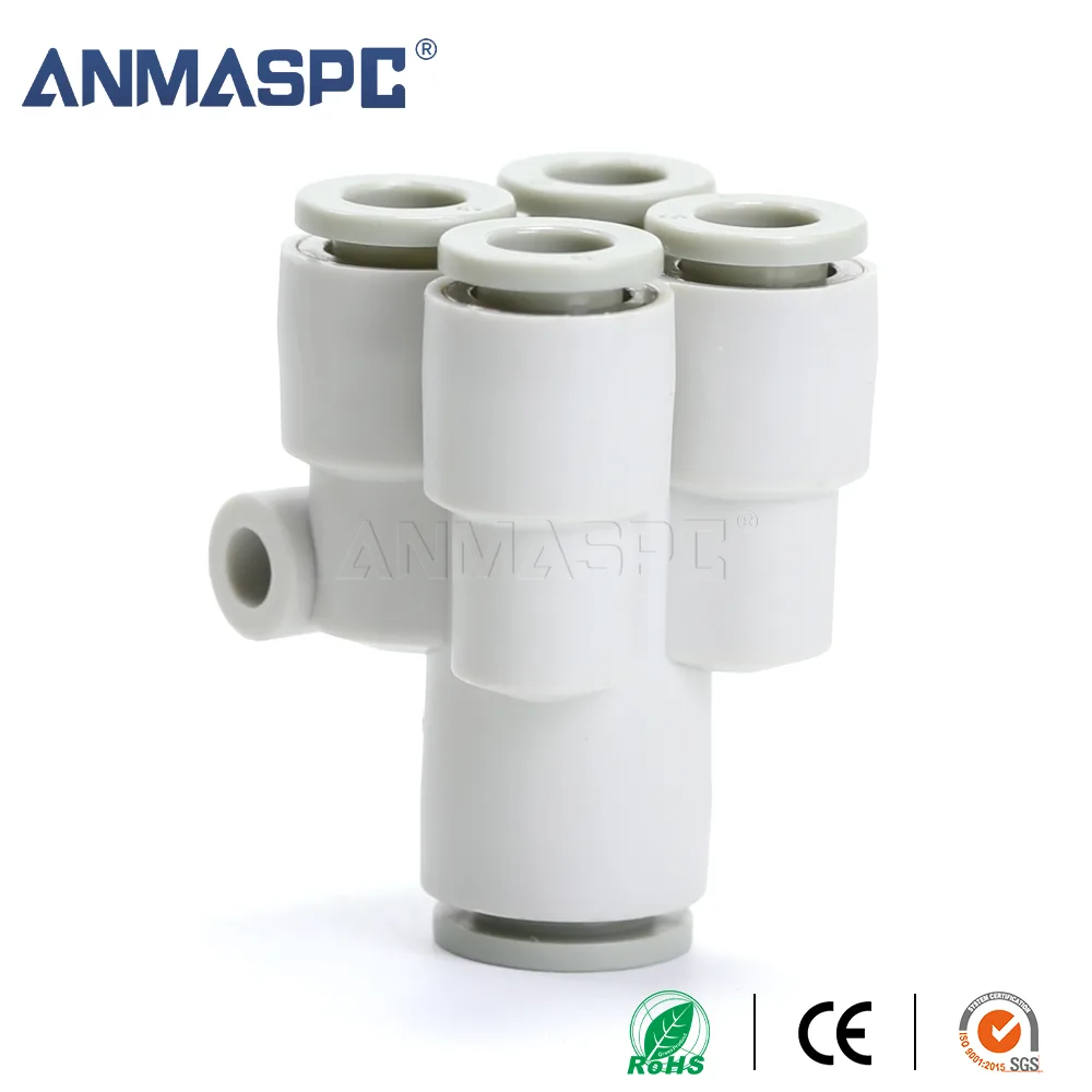
A straight body is not defined only by its outside shape. Confirm the port thread, tube OD, internal bore, seal compound, body material, medium, operating pressure and temperature range, and any flow-direction marking before approving Pneumatic Straight Fittings. Pressure loss depends on the internal path, fittings upstream and downstream, tubing length and the actual demand; thread size alone cannot predict it. For directional components, follow the arrow or pneumatic symbol. For a plain straight connector, use the supplier documentation to establish whether direction is unrestricted.
| Interface or duty | Record in the maintenance or procurement file | Why a visual match is insufficient |
|---|---|---|
| Tube side | Measured OD, metric or inch series, material and surface condition | Collet grip and seal geometry are dimension-specific |
| Port side | BSPP, BSPT, NPT or other stated thread, size, pitch and sealing method | Look-alike threads may engage without making a pressure-tight joint |
| Operating duty | Medium, working pressure, temperature range, cycling and external exposure | Body and seal suitability depend on the complete envelope |
| Flow path | Required downstream behavior, bore information and any flow data conditions | A restrictive internal path can change actuator response even without an external leak |
| Service method | Isolation point, tube-cutting tool, insertion method and post-repair check | Uncontrolled service can damage a new seal or leave contamination inside the line |
When a replacement is needed, start with the documented pneumatic parts range and then request the exact variant’s drawing and limits. The products directory is a catalogue route, not proof that two visually similar parts are interchangeable.
What do ISO standards change about a leak investigation?
ISO 4414:2010 sets general rules and safety requirements for pneumatic fluid-power systems and their components. ISO 12100:2010 provides machinery risk-assessment and risk-reduction principles. They support controlled isolation, documented hazards and safe verification, but neither standard supplies a universal tightening value or certifies a particular fitting. ISO 228-1 and ISO 7-1 describe different BSP-related thread concepts, while ASME B1.20.1 covers general-purpose inch pipe threads such as NPT.
For flow questions, use supplier data or a repeatable method with stated conditions; the U.S. Department of Energy’s compressed-air resources explain why leakage and pressure management should be treated as system issues. Keep the standard edition, part number, tube pairing and inspection result with the repair record. Unsupported claims about pressure, temperature, certification or compatibility can create procurement and safety risk even when the connector appears to work during a brief test.
How should a technician decide between repair and replacement?
- Make the system safe. Follow the machine isolation procedure, shut off the supply and release stored pressure before touching the connector.
- Freeze the evidence. Photograph the installed orientation if permitted, record tube OD and thread marking, and note when the leak appears in the cycle.
- Correct preparation first. Cut back damaged tube, clean the interface and reseat it using the fitting instructions.
- Replace on evidence. Replace the fitting when the body, thread, collet or accessible seal is damaged, when leakage returns after correct preparation, or when the part cannot be identified.
- Verify the assembly. Use the approved leak and functional checks at operating demand, and document the exact replacement and conditions.
For systems that also use controlled air valves, the site’s guide to solenoid valve types helps keep valve direction and fitting interfaces in the same review. A fitting investigation should end with a known interface, not just a quiet hiss at one pressure.
Frequently asked questions about Pneumatic Straight Fittings
Which sealing method is best for the threaded side of the Pneumatic Straight Fittings?
The correct method is the one specified for the identified thread and fitting: it may involve a compatible thread sealant, a washer, or a design that seals elsewhere. Confirm whether the port uses a parallel or tapered thread before applying material, and keep sealant away from the air path. More sealant or more torque cannot compensate for a wrong thread.
How do you measure the Pneumatic Straight Fittings before ordering replacement parts?
Record the tube outside diameter and series, port thread designation and size, fitting orientation, body and seal details, and the operating medium and envelope. Use a drawing or gauge for pitch and taper rather than relying on a ruler or visual comparison. Order against the complete part description and confirm the current datasheet.
What causes a tube to release from the Pneumatic Straight Fittings under vibration?
Common causes include wrong OD, incomplete insertion, a damaged tube end, worn gripping parts, unsupported routing, or side-load from a tight bend. Isolate the system, inspect the tube and collet, correct the routing and use the specified retention check. A clip does not make an unapproved tube-fittings pairing acceptable.
Is plastic, brass or stainless steel better for the Pneumatic Straight Fittings application?
There is no universal material winner. Select the body and seal from the documented medium, pressure, temperature, cleaning, corrosion, mechanical and weight requirements, then verify the exact grade or compound offered for the part. Material alone does not establish a safe operating limit.
How do you check flow direction and airflow loss through the Pneumatic Straight Fittings?
Check the pneumatic symbol, body arrow and supplier documentation to determine whether the component is directional. For airflow loss, compare data measured under stated conditions or measure upstream and downstream pressure at a repeatable operating demand. A static no-flow reading cannot show the pressure loss of a working circuit.
What signs show that the collet or O-ring in the Pneumatic Straight Fittings needs replacement?
Sticking or uneven collet movement, damaged gripping features, a cut or displaced accessible O-ring, recurring leakage after a square cut and correct insertion, or unreliable tube retention are replacement signals. Replace the complete fitting unless the manufacturer identifies a service part and supplies an approved procedure. Do not probe or scratch an accessible seal while investigating.
References
- ISO 4414:2010, Pneumatic fluid power – General rules and safety requirements for systems and their components.
- ISO 12100:2010, Safety of machinery – General principles for design – Risk assessment and risk reduction.
- U.S. Department of Energy, Industrial Technologies Office, compressed-air systems resources.
- ISO 228-1, Pipe threads where pressure-tight joints are not made on the threads.
- ISO 7-1, Pipe threads where pressure-tight joints are made on the threads.
Leaking Pneumatic Straight Fittings are best solved by proving the interface in sequence: identify the thread and sealing method, measure the tube OD, inspect the cut and seating, remove vibration loads, and then confirm that the replacement fits the documented pressure, temperature, medium and flow duty. Tightening is only an action, not a diagnosis. The inspection must be performed with the air line isolated and depressurized, and the final check must use the machine’s approved procedure at the relevant operating demand. When the records are complete, Oulu / ANMASPC can support the next sourcing step through its pneumatic parts range and current product documentation. Contact the supplier with the measured interfaces and duty conditions so the selected part can be reviewed as an assembly rather than guessed from appearance.