
A network link can fail acceptance even when every cable and connector looks new. A buyer may specify a familiar modular plug for a copper run, yet overlook whether it fits the cable’s conductor type and diameter; a fiber installer may select the correct connector shape but leave an end face contaminated. The resulting rework is not simply a question of buying a better plug. It starts with identifying the medium, matching every mating interface, using the intended termination process and testing the completed link. This guide separates those decisions so an installer or procurement team can ask for evidence rather than relying on connector appearance.
Özet: Internet connectors and plugs are not interchangeable: copper twisted-pair links use matched modular connecting hardware, while optical links use fiber connectors and adapters with compatible connector and end-face types. ISO/IEC 11801-1 addresses generic cabling systems, and the ANSI/TIA-568 series distinguishes copper from optical-fiber cabling requirements. Specify the complete link and its environment first; then check cable-to-connector compatibility, terminate to the manufacturer’s instructions, and request the appropriate copper certification or fiber inspection and loss-test record. A connector that fits mechanically does not, by itself, prove link performance.
Match the Connector to the Cable and Equipment Link
In everyday purchasing, “internet plug” often means the eight-position modular plug on a twisted-pair Ethernet patch cord. The name says little about the actual channel: an outlet jack, patch panel and equipment cord may each be part of it. A network connector must match its mating hardware and the specified cable, including category, shield arrangement, conductor construction and the connector maker’s accepted wire range. Solid installation cable and stranded patch-cord cable are not automatically terminated with the same plug. The relevant ANSI/TIA-568.2-D scope is balanced twisted-pair cabling and components, not a universal approval of any plug stamped with a category label [1].
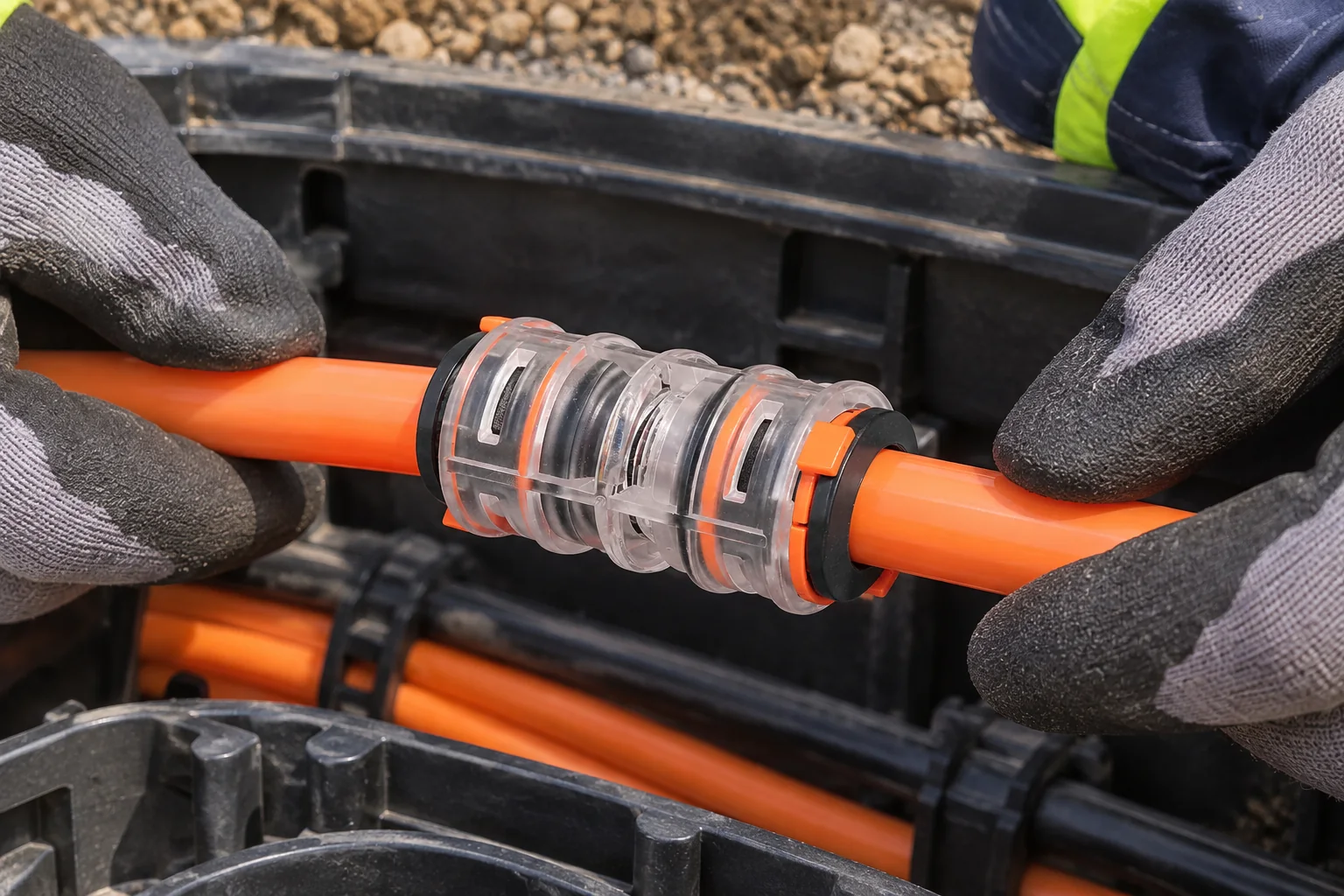
Optical links have a different boundary. LC and SC describe connector form factors, while single-mode or multimode fiber, adapter fit and end-face geometry also matter. Do not mate angled-polish (APC) and ultra-physical-contact (UPC) end faces merely because their housings appear to fit. Confirm the transceiver and patch-panel interface, cable type and connector designation on the equipment documentation. The fiber connector is part of the optical path; a closure or microduct fitting protects or routes cable but does not replace an optical termination. Thus, selecting internet connectors and plugs starts with the physical layer, not the familiar shape of a housing.
Check Termination Quality Before Accepting the Link
For a copper modular plug, the key question is not whether the latch clicks. The selected plug must accommodate the cable jacket and each conductor, maintain the pair geometry through termination and follow a consistent T568A or T568B pin assignment at the relevant interfaces. A mixed or poorly terminated pair can produce a wiring-map fault or excess transmission loss. If field termination is planned, check the plug maker’s cable specification and tooling instructions, then certify the installed cabling against the design category and test limit. A continuity light alone does not demonstrate the full transmission performance of the channel.
For fiber, contamination or damage at a connector end face can add loss or reflection even when the connector appears seated. Inspect, clean if necessary, and reinspect before mating; protect unused ends and document the test method and acceptance limit chosen for the project. Fluke Networks’ public testing guidance distinguishes inspection and loss testing from simply observing whether traffic passes [3]. The required test setup also depends on whether the acceptance boundary is a permanent link, channel or optical cable plant.
These mistakes have different cost paths. The connector itself may be inexpensive relative to identifying an intermittent fault, returning to an inaccessible outlet, replacing a patch lead or retesting a route. Compare the cost of the completed, documented link rather than plug unit price alone. This is a total-cost framework, not a claim that any one connector type always costs less.
| Decision | Twisted-pair copper | Optical fiber |
|---|---|---|
| Match first | Cable and connecting-hardware category, shield, conductor construction and wire range | Fiber type, connector form, polish, adapter and equipment port |
| Termination control | Approved plug and tool, pair placement, strain relief and pin assignment | Approved connector process, bend handling and end-face inspection |
| Kabul kanıtı | Wire map and category-specific transmission certification to the agreed limit | Inspection and optical-loss results to the agreed method and budget |
| Hidden cost if mismatched | Re-termination, inaccessible-channel troubleshooting and repeat testing | Cleaning, replacement, reconnection and repeat optical testing |
Specify Connectors for the Installation Boundary
The path surrounding a connector matters as much as the visible plug. ISO/IEC 11801-1 describes generic cabling for customer premises, including the system context in which components are selected [2]. It should not be read as a certificate for a particular product. For a buried or outside-plant fiber route, specify the duct, closures, seals, cable and accessible termination points separately. A sealed duct joint does not prove the optical connector’s loss, and a passing optical test does not establish the duct’s environmental sealing.
| Uygulama | Connector or interface question | Talep edilecek kanıt |
|---|---|---|
| Office copper outlet or patching | Does each plug or jack suit the cable, category and shielding scheme? | Component specifications and the agreed installed-link test report |
| Equipment fiber patching | Do fiber type, LC/SC format and polish match both ports? | Equipment interface documents and inspected, tested connections |
| Outdoor fiber duct and closure route | Where are the duct seal, splice protection and optical mating points? | Route drawings, fitting/closure specifications and optical test records |
For more on the protected pathway, see microduct connectors in FTTH networks; the duct connection is a different component decision from the optical plug. The choice between air-blown or traditional cabling can likewise change access and future installation planning, but it does not remove the need to specify the final optical interface.
Request the Applicable Standards and Test Records
Use standards by scope, not as decorative badges. ANSI/TIA-568.2-D concerns balanced twisted-pair cabling and components; the appropriate project test limit must reflect the installed design and the applicable edition. ISO/IEC 11801-1 sets generic cabling system requirements for customer premises and does not certify an individual network connector. Optical test requirements and acceptance limits must be separately stated in the project specification; inspection guidance and a tester’s result are not themselves a manufacturer certification. Before ordering, confirm the destination-market contract requirements, intended environment and any claims that procurement expects to substantiate. An unsupported “compliant” label can leave both acceptance criteria and responsibility for retesting unclear.
A practical submittal should identify the standard and edition used, the link boundary, component data sheets, cable/connector compatibility and the selected field-test method. Ask who will supply and retain the results. This makes a failed link actionable: it is possible to separate a wrong interface from a termination defect or an issue elsewhere in the cable plant.
Verify the Medium, Interfaces, and Acceptance Test Before Installation
- Map the medium and mating points. Record copper or fiber and both equipment interfaces; distinguish the network connector from any patch lead, splice protection or duct fitting in the route.
- Check the complete compatibility list. For copper, confirm cable category, shield, solid/stranded construction and conductor range against the plug data sheet. For fiber, confirm fiber type, connector format, polish and adapter.
- Define the test before installation. State the link boundary, method, limit and record format so a pass/fail decision is not improvised after termination.
- Keep pathway hardware distinct. Select closures and microduct fittings for their documented cable-path duty, then select optical connectors for the equipment interface. The related guide on how to choose the right connector can help organize this specification discussion.
Oulu / ANMASPC supplies microduct connectors and related fiber-network pathway components. Where the project crosses from a duct route to a termination point, request the exact product data and installation instructions for each part instead of assuming one fitting can serve both jobs.
Sıkça sorulan sorular
Are all Ethernet plugs interchangeable?
No. A modular plug must match the cable’s relevant category, conductor construction and size, as well as the chosen shielding scheme and installation method. Check the maker’s cable compatibility and approved tooling before crimping.
Can a copper cable pass a simple continuity test but fail network certification?
Yes. Continuity or a basic wire map does not measure every transmission parameter required by the selected category test limit. Specify the required link test and keep its report with the installation records.
What is the difference between a fiber connector and a microduct connector?
A fiber connector mates an optical fiber at an adapter or equipment port. A microduct connector joins or seals the pathway carrying a cable or blowable fiber; it is not an optical mating interface. Specify and verify each separately.
Can APC and UPC fiber connectors be mated?
They should not be treated as interchangeable. Their end-face geometry differs, so confirm the polish specified at both sides of the interface and use compatible mating hardware. Inspect the end faces before connection.
Is a higher-category plug enough to upgrade an Ethernet link?
No. The channel includes cable, jacks, patch cords and installation quality, and its claim needs the appropriate end-to-end test. Start with the target system specification, then select every component for that design.
What records should accompany a fiber connector installation?
Keep the connector and fiber specifications, inspection record where required, and optical test results referenced to the agreed method and loss budget. Also document the tested route and its endpoints so a later fault can be located without guessing.
Kaynakça
- Telecommunications Industry Association, Standards program. Consult the applicable ANSI/TIA-568.2-D balanced twisted-pair cabling specification and project edition.
- ISO/IEC 11801-1:2017, Information technology — Generic cabling for customer premises, Part 1: General requirements. Check the current edition and amendments for the project.
- Fluke Networks Knowledge Base. Public guidance on copper cabling certification and fiber inspection/testing; apply the project-specified procedure and limits.
Choose and Test the Complete Connector Interface
The useful distinction is between a connector that physically fits and a link whose whole interface is specified and tested. Choose internet connectors and plugs by identifying copper or fiber first, then document the cable and mating hardware, choose a compatible termination method, and agree on the acceptance test before installation. Never skip an end-face inspection or substitute a continuity check for the transmission evidence the design requires. Outdoor pathways add another boundary: duct joints and closures protect the route, while optical connectors establish the equipment connection. Procurement should ask for separate data and records for each. Oulu / ANMASPC’s microduct and fiber-network product range can support the pathway portion of that decision; contact the team with the route drawing and interface requirements to identify the relevant components.


