
When a network planner in Leeds found that a newly occupied building needed more fiber strands than the original schedule allowed, the team first considered replacing the cable already specified for the route. In this illustrative planning scenario, that change immediately exposed a problem: the pathway had no spare capacity for another pull. The issue was not a defective cable; it was the choice between filling a route now and reserving a usable pathway for later installation.
Summary: Air-blown cabling installs suitable fiber units into a prepared microduct using controlled airflow, while traditional cabling generally installs the selected cable into its pathway during the initial build. Neither method wins by default. ITU-T L.79 addresses optical-fiber cable elements intended for microduct blowing, and IEC 60794-5-20 covers outdoor microduct fiber units and related microduct products; neither guarantees a distance or speed for a particular route. Map the route, decide when capacity is needed, and obtain a documented installation method and whole-life cost comparison before buying.
Compare Pathway Capacity With When Fiber Is Needed
“Traditional cabling” can mean a cable pulled through conduit, placed in a tray, or otherwise installed at construction; its cable type and pathway determine the actual method. Air-blown fiber separates pathway placement from fiber installation: microducts are installed first, and a compatible fiber unit can be blown into an available duct when needed. Both approaches still require protected pathways, access points, bend management, terminations, testing, and records.
The useful distinction is therefore timing, not an assumed difference in optical performance. A project that knows its near-term strand count and can access a straightforward route may favor an initial cable installation. A phased campus, estate, or FTTH distribution network using microduct connectors may value spare, tested ducts for later fiber placement. Spare duct is only useful if it remains continuous, clean, identifiable, and compatible with the fiber unit and blowing equipment.
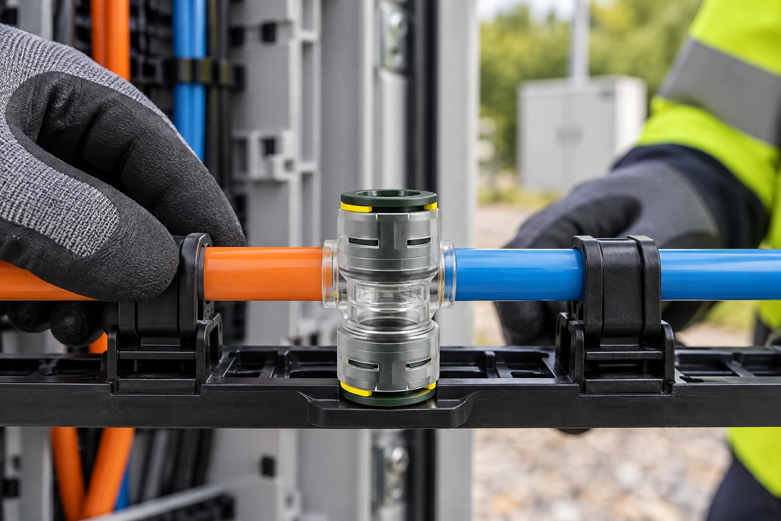
Compare Duct Preparation and Cable-Installation Work
A conventional pull depends on the pathway geometry, cable construction, pulling tension limit, bend radius, lubricant if permitted, and handling plan. A blown route instead depends on the duct bore and condition, fiber-to-duct fit, bends, joint integrity, compressor and blowing-equipment setup, and the manufacturer’s distance and pressure limits. A blowing machine does not overcome crushed duct, water, sharp transitions, or an unsealed joint.
ITU-T L.79 defines the context for cable elements used in microduct blowing applications. IEC 60794-5-20:2014 specifies outdoor microduct fiber units, microducts, and protected microducts for blowing installation. These are product and system references, not universal field acceptance values. Ask suppliers for the exact component datasheets and use the equipment and cable makers’ installation instructions to set a route-specific method, then verify duct continuity and fiber performance after work.
| Decision point | Air-blown fiber in microduct | Traditional cable installation |
|---|---|---|
| Initial scope | Install and verify the duct route; place fiber units now or in later phases. | Install the selected cable and pathway for the present build. |
| Future capacity | Available only where suitable spare duct, access, and route records remain. | Available through planned spare fibers or an accessible pathway with capacity for another cable. |
| Installation constraints | Duct fit, continuity, joint sealing, bends, and blowing-equipment limits need control. | Cable pulling tension, bend radius, pathway loading, and handling need control. |
| Cost tendency | Additional duct, fittings, access, and specialized installation can raise initial scope; deferred fiber may avoid opening a route later. | Can be simpler for a defined one-time installation; adding capacity later may require another cable or pathway work. |
| Testing and repair | Document duct integrity before blowing and test the finished optical link; repair access still matters. | Test the installed optical link and retain access for fault location and repair. |
Compare Pathway and Future Expansion Costs Over the Planning Period
Do not compare a unit price for fiber with a quoted price for an entire microduct system. A fair estimate includes pathway construction, duct or conduit, cable or fiber unit, connectors and closures, equipment and crew, access chambers, acceptance tests, records, and future intervention. Avoid a claimed payback period until the number, timing, and length of future additions are known. Any savings from deferring fiber placement depend on whether the preinstalled duct remains usable.
For a scenario analysis, estimate total cost = initial pathway and installation + scheduled fiber placements + testing and documentation + expected access or repair work for each option over the same planning horizon. Treat probabilities and future crew rates as assumptions, not supplier facts. Sensitivity-test at least a no-expansion case and a plausible phased-expansion case; this often changes the decision more than a small difference in material price.
| Project condition | What to check | Likely decision effect |
|---|---|---|
| One known capacity requirement | Fiber count, pathway availability, access, and pulling limits. | A single conventional installation may be the simpler baseline. |
| Phased tenants or service areas | Dates, independent routes, spare duct count, and handhole access. | Separating duct and fiber placement may deserve a costed option. |
| Constrained bends or long route | Route survey, duct bore and condition, cable or fiber-unit limits, and trial method. | Neither method should be assumed feasible from nominal length alone. |
| Buried or exposed joints | Specified connector environment, sealing evidence, and repair accessibility. | Joint selection and verification can govern blowing feasibility and maintenance cost. |
| Uncertain future demand | Cost of spare fiber now versus spare usable duct and later mobilization. | Compare scenarios instead of claiming an automatic return on investment. |
Document the Duct Interfaces and Test the Installed Route
Start procurement with a route drawing that shows each section, bend, access point, duct size, joint, transition, and termination. Select the fiber unit and microduct as a documented system; nominal duct diameter alone does not establish usable clearance. Review plastic air duct selection alongside the fiber-unit specification, environmental exposure, and local installation requirements. Confirm pull or blow limits with the actual manufacturers before crews mobilize.
At every microduct joint, check both duct outside diameters, insertion method, application environment, and any sealing or retention requirements against the exact fitting datasheet. Keep the open duct protected, make clean square cuts as instructed, and record the documented acceptance test. The fitting is only one part of the air path; a splice box in a blown-fiber installation also needs accessible placement and an appropriate cable-management plan.
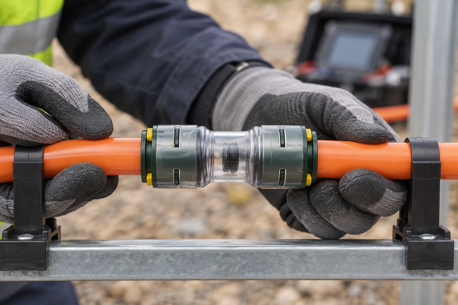
Finally, separate references from approvals. ITU-T L.163 concerns criteria for optical cable installation with minimal existing infrastructure; it does not certify a proposed route or establish a universal installation speed. BICSI’s published standards portfolio can inform the applicable cabling design and administration scope, but the contract must name the particular standard and edition. A supplier’s statement that a product is “standard compliant” is not a substitute for the applicable test report, installation instructions, and project acceptance criteria. Confirm requirements for the destination market and intended installation with the designer and authority having jurisdiction.
Frequently Asked Questions
Is air-blown fiber always cheaper than traditional cabling?
No. Duct infrastructure, fittings, access points, and specialized equipment can increase the initial scope, while later fiber placement may avoid disruptive pathway work. Compare the same route and planning horizon under realistic expansion scenarios.
Can existing conduit be used for air-blown fiber?
Possibly, if a compatible microduct can be installed and the resulting route meets the fiber-unit and equipment makers’ requirements. Inspect bends, fill, access, continuity, and condition; ordinary conduit by itself is not automatically a blowable microduct.
How far can fiber be blown in one operation?
There is no reliable universal distance. Duct bore and friction, route geometry, joints, fiber-unit design, air supply, and equipment settings all matter. Ask the installation contractor to validate the actual route and use the relevant manufacturers’ limits.
Does traditional cabling prevent future expansion?
No. Spare fibers and a properly sized, accessible pathway may cover anticipated growth. If later pulls or new civil work would be difficult, compare that provision with reserving verified microducts.
What should be tested before fiber blowing?
Verify that the duct is identified, continuous, clean, correctly joined, and fit for the planned installation. Use the project’s and component manufacturers’ documented test method and acceptance criteria; do not borrow a pressure or hold time from an unrelated fitting.
Do standards prove that a connector will seal on site?
No. A relevant standard describes a scope and requirements, while the exact connector’s datasheet and test evidence establish its claimed application. Installation quality and a documented field acceptance test are still necessary.
References
- ITU-T L.79, Optical fibre cable elements for microduct blowing-installation application.
- IEC 60794-5-20:2014, Outdoor microduct fibre units, microducts and protected microducts for installation by blowing.
- ITU-T L.163, Criteria for optical cable installation with minimal existing infrastructure.
- BICSI standards portfolio; select the applicable document and edition for the project.
Bottom line: Design the pathway for the next realistic change, then choose the cable-installation method that can be verified on that route today.
For a phased microduct route, compare the duct, fiber unit, and joints as a system. Review Microduct Connector’s microduct connector range and contact the team with duct sizes, route conditions, and acceptance requirements for a documented fit check.


