When a network contractor in Oulu prepared an air-blown-fiber section for handover, the crew joined two ducts, began the pressure check, and saw the gauge fall almost immediately. The connector had been selected from a nominal duct label, while the actual outside diameters and the cut quality had not been verified. Replacing the fitting alone was not the lesson: once the team measured the duct interfaces, prepared square ends, and followed a documented test plan, the section was ready for installation.
Резюме: The best microduct fittings are selected by function, actual duct outside diameter (OD), route conditions, and a defined acceptance test—not by appearance or a generic “microduct” label. Duct OD governs the fitting interface; duct inside diameter (ID) helps determine the passage available to the cable. IEC 60794-5-20 covers microduct cabling intended for installation by blowing, while connector claims must still be supported by model-specific documentation. Specify each port, inspect every joint, and test the completed section before fiber blowing.

Why microduct fitting selection affects project economics
Microduct fittings are interfaces in a pressurized installation path. Straight connectors extend a same-size route; reducers manage a planned size transition; branch fittings organize distribution; and plugs, end caps, or gas-block components close or isolate sections where the design requires them. A mismatch can impair air retention, create an obstruction, or make a fault difficult to locate after civil work is complete.
Procurement should consider total installed cost, not unit cost alone. A poorly specified component can lead to retesting, downtime, and delayed acceptance. The project specification—not a generic rule of thumb—must define the applicable test pressure, duration, and pass/fail limit.
| Selection dimension | Best-practice question | Commercial consequence |
|---|---|---|
| Compatibility | Does each port match the confirmed duct OD? | Reduces wrong-part returns and site rework |
| Route function | Must the route continue, reduce, branch, or terminate? | Prevents a functional mismatch in the bill of materials |
| Installation quality | Can the duct be cut, cleaned, and seated as instructed? | Supports repeatable acceptance checks |
| Documentation | Are installation and compatibility details available? | Improves traceability for contractors and owners |
| Lifecycle access | Will the joint remain inspectable or serviceable? | Limits investigation time during future alterations |
Match the fitting type to the route design
Begin with the drawing and identify the purpose of every joint. A product category can help a buyer compare available forms, but each purchase line should state the exact interface required on both ends. Do not assume that ducts with similar names, or metric and inch labels that look close, will seat correctly in the same fitting.
Use a straight connector for two duct ends with the same specified OD. A straight microduct connector is usually the cleanest choice for an in-line continuation, provided the duct ends are undamaged and fully inserted. Use a reducer only for an engineered transition between stated sizes; confirm which port receives each duct and review the downstream cable route. A microduct reducer connector should never be used to compensate for an uncertain measurement.
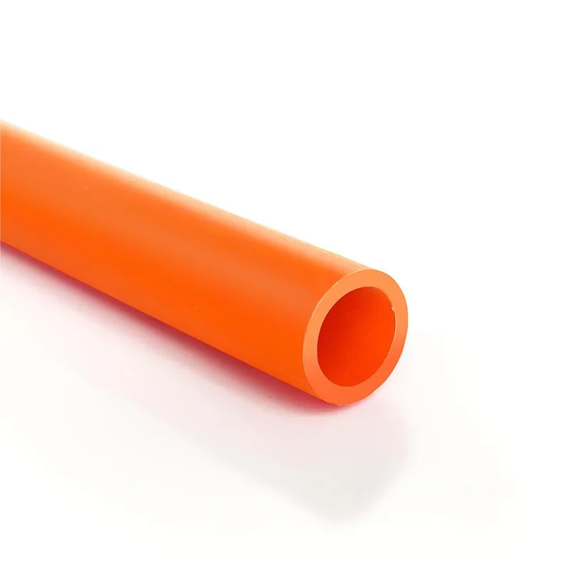
For spare routes and section boundaries, distinguish closure from pass-through function. A plug or end stop closes an unused path; a gas-blocking component has a defined isolation purpose and should be selected only where the network design calls for it.
| Fitting type | Appropriate use | Key verification before ordering |
|---|---|---|
| Straight connector | In-line connection of equal-size ducts | Both duct ODs, cut condition, insertion requirement |
| Reducer | Designed transition between two specified duct sizes | Large/small port orientation and cable-path review |
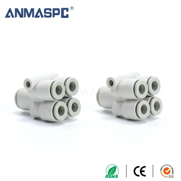
| Branch fitting | Planned distribution to multiple routes | Port labels, route map, access for future work |
| End stop or plug | Closure of a spare or unfinished duct | Duct size and whether future passage is required |
| Gas-block component | Isolation where the engineering design specifies it | Location, duct interface, and installation instruction |
Control installation and acceptance before fiber blowing
A sound component can still fail when the duct end is oval, contaminated, poorly cut, or not fully seated. Follow the fitting manufacturer’s instructions: cut the duct squarely, remove debris, avoid deforming the tube, and insert it to the stated stop where applicable. A visual insertion mark can assist inspection, but it does not replace the project’s approved pull check or air-tightness test.
Before blowing fiber, isolate the section and carry out the pressure-decay or other specified test method. Record the route section, test medium, stabilized pressure, duration, instrument, and result. If a test fails, inspect the setup, duct ends, seating, and component condition systematically; raising pressure without diagnosis can obscure the real cause. The test method is not a universal product certification or an automatic rating for every fitting.
Standards, claims, and supplier evidence
IEC 60794-5-20 addresses microduct cabling intended for blowing; IEC 60794-1-2 provides basic optical-fiber-cable test procedures; and ITU-T L.35 gives installation guidance. They support disciplined system specification, but do not themselves certify a fitting as leak-proof, pressure-rated, or fit for every environment.
Request exact product documentation, duct interfaces, installation instructions, and supportable test information. Destination-market rules, client specifications, and the claimed application determine the evidence required; do not fill gaps with unsupported marketing claims.
A procurement checklist for the best option
- Map every joint by location and function before issuing the bill of materials.
- Record duct manufacturer, nominal size, measured OD, wall construction, and ID where cable passage must be assessed.
- Request fitting documentation for the exact duct combination, rather than accepting a broad compatibility statement.
- Set the inspection and pressure-test record before installation begins.
- Keep route labels and spare-path decisions visible for the handover file.
For a specification-led review in Oulu or elsewhere, compare the route needs with documented microduct gas-block options and connector configurations. The productive supplier discussion begins with dimensions, function, route conditions, and required documentation.
Часто задаваемые вопросы
How do I choose the best microduct fittings?
Choose by confirmed duct OD at every port, the fitting’s intended function, route environment, and the project’s acceptance method. Compare model-specific documentation and installation instructions, then verify the completed joint before fiber blowing.
What size microduct connector do I need?
Select a connector port that matches the actual outside diameter of the duct it receives. Also confirm the duct ID and cable route, because a fitting can match the OD while the overall pathway is still unsuitable for the planned cable installation.
Are all microduct fittings compatible with HDPE ducts?
No. Compatibility depends on the fitting design, the duct OD, wall construction, and the manufacturer’s stated application. Do not treat “HDPE” as enough information; verify the exact duct and fitting combination in the supplied documentation.
How do microduct fittings affect fiber blowing?
They form part of the air path and cable route, so poor sizing, debris, damage, or incomplete seating can contribute to pressure loss or an obstruction. Test the completed section under the approved project method before a cable-blowing run.
What causes a microduct connector to leak?
Common causes include an incorrect duct OD, an uneven or damaged cut, contamination, incomplete insertion, component damage, or a flawed test arrangement. Investigate each condition against the manufacturer’s instructions and project test record rather than assuming the connector is defective.
Should I use straight connectors, reducers or end stops?
Use straight connectors for equal-size in-line ducts, reducers for a specified size transition, and end stops to close a route that is not meant to pass cable. The route drawing and measured duct interfaces should decide the component, not availability alone.
Ссылки
- IEC 60794-5-20 — Optical fibre cables: Microduct cabling for installation by blowing
- IEC 60794-1-2 — Optical fibre cables: Generic specification and basic optical cable test procedures
- ITU-T L.35 — Installation of optical fibre cable networks
- BICSI Standards — telecommunications infrastructure standards information
In fiber construction, a fitting is a controlled interface, not a minor accessory. When your bill of materials is ready, review Microduct Connector’s microduct fittings and contact the team with your duct dimensions, route drawing, and documentation requirements.