
When a network planner is asked to add fiber through an existing underground route, the visible failure may be simple: the air-blown microfiber optic cable stops before the planned access point. The cause is often upstream selection or preparation rather than a defective cable. A poorly sealed joint, an unverified bend, an obstructed microduct, or an incompatible cable-and-duct combination can consume the installation margin before the blower is started. This guide explains how air-blown microfiber optic cable moves through a microduct, what the crew should confirm at each stage, and where the method is appropriate. It also separates standards-based requirements from project assumptions, so the installation plan can be checked before equipment and labor are committed.
Кыскача мазмун: Air-blown microfiber optic cable is installed by using compressed air to move a lightweight cable through a prepared microduct, allowing fiber capacity to be deployed in stages instead of placing every fiber on day one. The relevant distinction is between the cable and the outdoor microduct system: the IEC standards catalogue (search for IEC 60794-5:2020) covers the applicable outdoor-microduct standard, while ITU-T Recommendation G.657 gives a relevant fibre and cable characteristic reference. Before blowing, verify duct continuity, internal cleanliness, cable/duct compatibility, bend and access conditions, and the sealing of every connection. Afterward, record the route, cable identity, end preparation, and test results rather than relying on a visual assumption that the cable reached its destination.
What is an air-blown microfiber optic cable?
An air-blown microfiber optic cable is a small, lightweight fibre cable designed to travel inside a microduct under a controlled air stream. The duct provides the route and physical protection; the cable provides the optical path. In a staged network build, spare duct capacity can remain available until demand justifies another installation. That changes the timing of capital expenditure, but it does not remove the need to engineer the route, because cable diameter, jacket friction, duct condition, bends, joints, and blowing equipment still interact.
The method is used in access, metropolitan, backbone, and FTTH contexts when a suitable microduct route is available. A deployment may use a single microduct, a bundle, or a protected HDPE arrangement. The correct choice depends on the route design and the cable system; a generic claim about maximum distance or universal compatibility would be misleading without the manufacturer’s installation limits and a route survey.
How does compressed air move the cable through a microduct?
The blower feeds air into the microduct while a drive mechanism introduces the cable. Air pressure acts on the cable surface and creates a forward force; the cable’s low mass and jacket design help it travel with less pulling tension than a conventional pull-in operation. The exact balance depends on the equipment, cable, duct geometry, air flow, and route condition. Installers should therefore use the cable and blowing-machine instructions for operating limits rather than copying a pressure or speed value from another project.
Which conditions control the result?
- Continuity: A blocked, crushed, flooded, or sharply deformed duct can stop the cable regardless of blower capacity.
- Geometry: Bends, changes in elevation, and access-pit transitions increase resistance and must be checked against the system design.
- Surface and lubrication: The cable jacket, duct material, and any approved lubricant must be compatible; an improvised lubricant can damage materials or change friction.
- Sealing: Leaks at connectors, plugs, or end fittings reduce the air stream and can make a sound route appear underpowered.
- Control: The crew should stop when operating limits, cable condition, or route evidence becomes uncertain, then diagnose the cause before restarting.
These checks are consistent with the systems view in IEC 60794-5: the microduct is part of the installation, not merely packaging for the cable. The standard’s scope should be read alongside the project specification and the cable supplier’s instructions; it is not a blanket certification of every assembled route.
What should be prepared before air blowing fiber?
Preparation is where most avoidable installation risk is removed. Start with the route drawing and confirm the actual duct identity at both ends. Prove continuity with the project’s approved mandrel, sponge, or other verification method, and document any obstruction instead of forcing the cable through it. Check that ducts are dry and that open ends are protected from dirt between preparation and blowing.
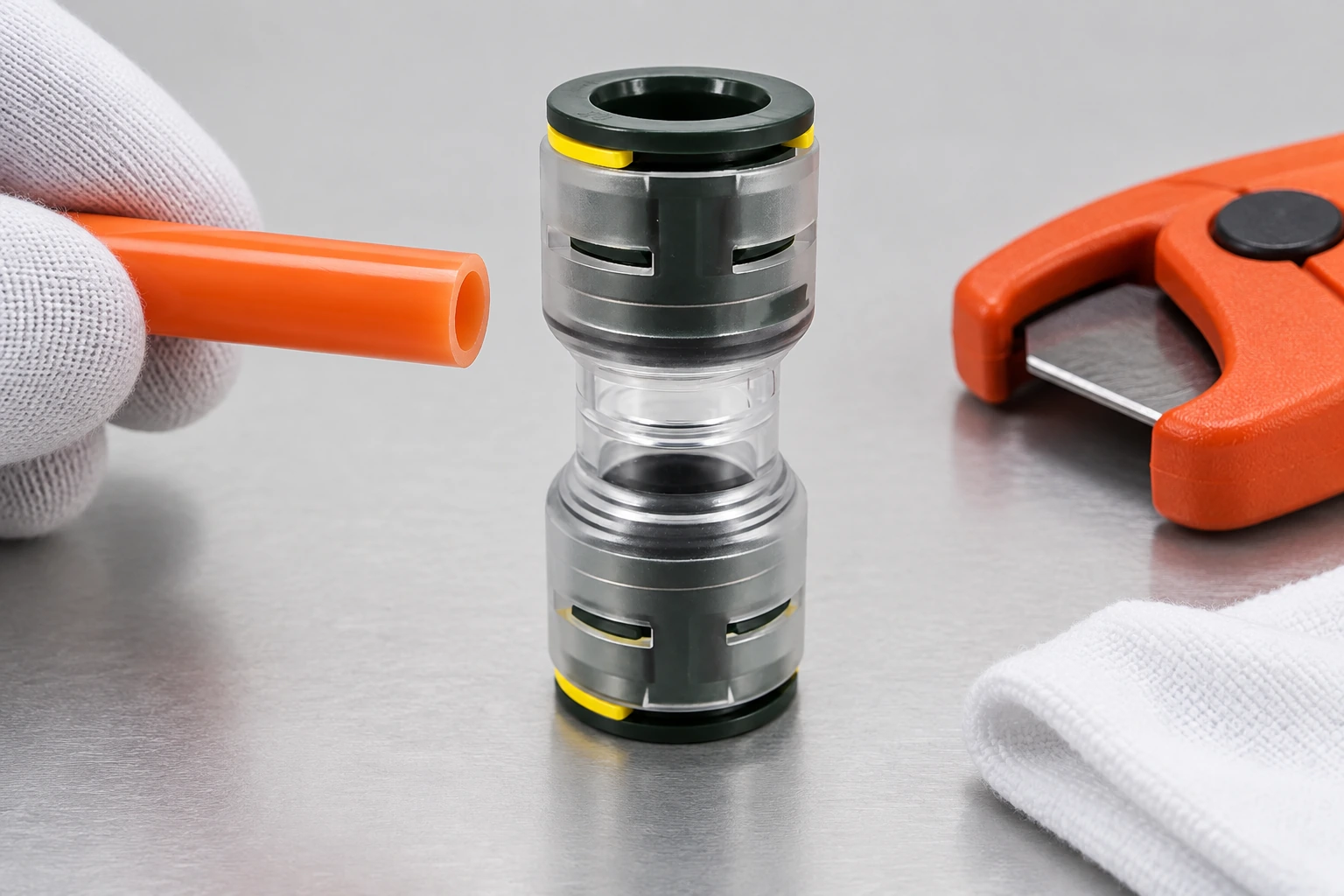
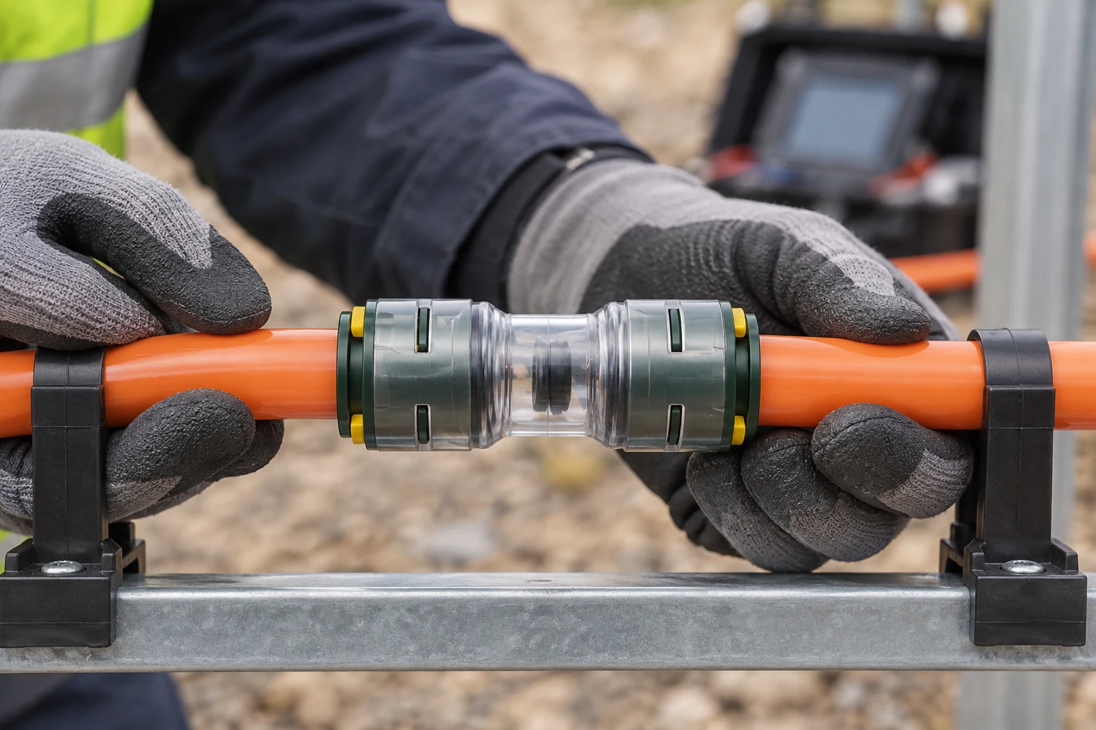
Inspect every joint and end. A connector should be fully seated, supported, and sealed for the intended environment. If the route includes a direct-buried section, confirm that the selected duct and connector arrangement is designed for that installation context; do not infer direct-burial suitability from appearance alone. The site’s HDPE microduct product page can be used as a starting point for comparing available duct formats, but the final selection still belongs in the project specification.
| Текшерүү | Кандай текшерүү керек | Сактап коюу үчүн далилдер |
|---|---|---|
| Duct identity and continuity | Correct route, open bore, no obstruction or crushing | Route mark-up and verification record |
| Ends and connectors | Square cuts, full seating, seals and plugs fitted for the environment | Installation photographs and joint log |
| Geometry and access | Bends, pits, entry direction, working space and cable handling path | As-built drawing and crew briefing |
| System compatibility | Cable diameter, duct type, blower interface and approved consumables | Supplier data sheets and approved method statement |
| Cleanliness and moisture | Open ends protected; bore condition suitable for installation | Inspection sign-off before blowing |
Which installation sequence reduces avoidable failures?
A controlled sequence makes the cause of a stoppage easier to isolate. First, brief the crew on the route and identify the planned stop points. Next, prepare and inspect the sending and receiving ends, install the correct interface hardware, and confirm that communications are available between access points. Start the blower within the supplier’s stated limits, watch the cable entry and exit, and pause if the observed behavior differs from the method statement. At the receiving end, protect the cable, leave the specified service loop, and seal the duct without imposing a sharp bend.
The route should then be labelled and recorded. A short installation record is more useful than a claim that the cable travelled “a long distance”: it should identify the duct, cable, date, crew, equipment, start and end points, and any interruption or corrective action. The construction method of air-blown optical cable provides additional background for aligning the field method with the project’s route and equipment plan.
When is air-blown fiber preferable to a conventional pull-in cable?
The method is attractive when a project needs staged capacity, wants to reuse a prepared duct route, or must limit repeated civil work. It can also support planned upgrades when the duct, cable family, access points, and records are managed as one system. It is not automatically the lower-cost option: the blower, trained crew, route preparation, connector quality, and troubleshooting time all belong in the total-cost calculation.
| Planning dimension | Air-blown microfiber approach | Conventional pull-in approach |
|---|---|---|
| Deployment timing | Can support staged placement when a suitable microduct is already available | Typically places the selected cable during the initial route build |
| Route dependency | Highly dependent on bore continuity, seals, bends and air-flow conditions | Highly dependent on pulling tension, bend control and route access |
| Upgrade planning | Future installations may be possible if spare duct capacity and records are preserved | Future capacity may require another cable, duct or civil intervention |
| Field equipment | Blower, cable drive, duct interface and trained operators | Pulling equipment, tension control and suitable access arrangements |
| Acceptance focus | Cable arrival plus duct sealing, identification and optical verification | Cable arrival plus tension, bend, identification and optical verification |
This is a planning comparison, not a performance ranking. The right method is the one that satisfies the route design, the cable specification, the civil constraints, and the project’s maintenance model. The site’s guide to air-blown or traditional cabling can help frame that decision before procurement.
How should a failed or short installation be diagnosed?
If the cable stops early, first stop the drive and make the route safe. Check whether the cable is damaged, whether air is escaping at an end or joint, and whether the measured route matches the drawing. A short installation is a symptom, not a diagnosis. Repeatedly increasing air or drive force can turn a correctable sealing or obstruction issue into cable or duct damage.
Use a symptom-to-action approach:
- No movement at entry: confirm the drive grip, cable alignment, duct interface, and initial seal.
- Movement followed by an abrupt stop: inspect the expected bend or access transition, then verify the bore and route length.
- Unstable movement or loss of air: inspect plugs, connectors, end preparation, and any open branch.
- Visible jacket damage: isolate the section, record the condition, and obtain supplier guidance before continuing.
If the cause cannot be isolated from field evidence, the responsible engineer or cable supplier should review the method statement. The direct-buried microduct product page is relevant only when the route actually uses that type of construction; it should not be treated as proof that another duct arrangement has the same duty.
Which standards and records matter at acceptance?
IEC 60794-5:2020 addresses outdoor microducts, while IEC 60794-1-1:2023 gives a generic specification framework for fibre-optic cables. Neither document replaces a project-specific installation method, and neither should be presented as a product certificate unless the applicable conformity evidence exists. The acceptance plan should state which optical tests, visual inspections, environmental checks, and records are required by the network owner.
At minimum, retain the route drawing, duct and cable identifiers, connector and seal records, installation date, equipment identification, interruptions, corrective actions, and the optical test results required by the contract. This documentation protects later maintenance work: a future crew can see which duct was used, where the cable ends are, and what was verified at handover.
What should buyers confirm before ordering?
- Match the cable and duct dimensions and confirm the supplier’s blowing interface and operating limits.
- Define the route environment: underground, direct-buried, access-pit, or another documented condition.
- Specify the connector, plug, sealing, and end-protection duties instead of selecting by nominal size alone.
- Require a method statement that names preparation, blowing, stopping, recovery, and acceptance steps.
- Agree what records and test results will be delivered with the installed route.
Oulu / ANMASPC lists microducts, connectors, duct plugs, and air-blown fiber tools as part of its product range. Buyers can review the products directory and then request compatibility information for the specific cable, duct, route, and installation method. Any certification or test claim should be confirmed in the current product documentation rather than inferred from a category listing.
Frequently asked questions about air-blown microfiber optic cable
What is an air-blown microfiber optic cable?
It is a lightweight fibre-optic cable designed to travel through a microduct using a controlled air stream and a cable drive. The duct and cable form an installation system, so route preparation and compatibility checks are essential. The cable supplier’s instructions determine the permitted equipment and operating limits.
How does compressed air move a fiber cable through a microduct?
Air pressure acts on the cable surface while the drive introduces it into the duct, creating forward movement with relatively low pulling tension. The result depends on duct geometry, seals, friction, cable construction, airflow, and equipment settings. Installers should follow the approved method statement instead of assuming one pressure or speed suits every route.
What microduct preparation is needed before air blowing fiber?
Verify the correct duct, prove continuity, remove or document obstructions, protect the bore from dirt and moisture, and inspect every end and connector. Confirm that cable, duct, interface hardware, and any lubricant are compatible. Record the checks before the blower is started.
Can air-blown fiber be installed in an existing duct?
It can be considered when the existing duct has adequate continuity, internal condition, space, access, and sealing for the selected system. “Existing” does not mean “ready”: the route still needs inspection and verification, and the owner may require evidence of its condition before installation.
Why does an air-blown fiber installation stop early?
Common causes include an obstruction, damaged or tight duct geometry, an unsealed joint, incorrect cable-to-duct selection, or a drive/interface problem. Stop safely, inspect the evidence, and isolate the cause before applying more force. A route record and expected access-point distances make diagnosis faster.
What should be checked after blowing fiber into a microduct?
Confirm the cable identity and endpoint, protect the service loop, inspect seals and bend control, label the route, and complete the optical and other acceptance tests required by the contract. Keep the as-built drawing and corrective-action record with the handover package. Cable arrival alone is not a complete acceptance decision.
Деректер
- IEC standards catalogue (search for IEC 60794-5:2020, Fibre optic cables — Part 5: Outdoor microducts).
- ITU-T Recommendation G.657, Characteristics of a bending-loss insensitive single-mode optical fibre and cable.
- FTTH Council Europe, publications and market resources.
Жыйынтык
Air-blown microfiber optic cable is best understood as a route-and-cable system, not a shortcut that removes installation engineering. The practical decision sequence is to confirm the duct, geometry, seals, cable compatibility, and access conditions; select equipment and consumables from the approved method; then verify the installed cable and document the route for the next crew. Do not compensate for an unexplained stoppage by simply increasing force or air. Check the evidence, protect the cable, and escalate when the operating boundary is unclear. Oulu / ANMASPC can support the component-selection stage through its microduct, connector, plug, and air-blown fiber product range. Review the product directory against the project specification, then contact the supplier for route-specific compatibility and documentation before ordering.


