
When a fiber installation supervisor in Leeds connected a new 12 mm route before a blowing run, the gauge began falling almost immediately and the cable stalled before the first chamber. The crew had replaced the connector twice, yet the rapid failure remained. The reversal came when they measured the actual duct outside diameter, re-cut an oval end square and selected a reducer for two different duct sizes: the root cause was specification and preparation, not simply a bad fitting.
The short answer is: An HDPE Microduct is a small-bore conduit designed to carry blown fiber, but its practical value depends on a continuous, clean and pressure-tight air path. Verify actual OD, ID, wall thickness and ovality; use the lower of the system and connector pressure limits for the project test; then document the hold time required by the network owner. IEC 60794-5 addresses microduct systems for air-blown optical cables, while EN 50411-2-8 provides a connector-performance framework. The most useful action is to qualify the duct-and-connector pair before field rollout.
What an HDPE Microduct does in an air-blown fiber system
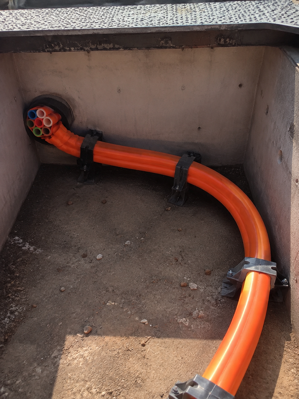
An HDPE Pipe microduct is normally a high-density polyethylene conduit, supplied as a single run or as a Micro Duct Bundle, that creates a protected pathway for future cable installation. Air blown fiber depends on pressure and airflow acting along that pathway; roughness, kinks, poorly aligned joints and leakage reduce the energy available to move the cable. A Micro duct tube is therefore more than a sleeve: its dimensional consistency and joints influence installation distance, compressor time and rework risk.
IEC 60794-5 sets out requirements for microducts used with air-blown optical cables; it does not make nominally similar ducts or connectors interchangeable. Before procurement, agree on OD, ID, ovality, pressure class, bend radius, temperature range and color identification. A 10 or 12 mm printed label is not a substitute for those values.
The commercial implication is straightforward: a low-cost part that creates a failed blowing run can cost more than a correctly specified assembly. Treat dimensional evidence and test records as total-cost controls, not paperwork.
Dimensions, duct condition and connector choice
Start with the duct, not the connector catalogue. Measure OD with an appropriate caliper at several positions on a representative reel; inspect the cut end for flattening, scratches and dirt; and compare the results with the fitting’s published gripping range. ID and wall thickness matter because a smaller-than-expected bore raises resistance to cable movement, while OD and ovality govern seal compression and collet grip. Record the lot and reel number so a later fault can be traced to the right material.
Straight connector or reducer?
A straight microduct connector is appropriate when both ducts have the same verified OD and compatible pressure requirements. It should preserve alignment and avoid an internal step at the joint. A reducer connector is for a controlled transition between two different ducts; confirm the exact size range at each port and the effect on the chosen cable and blowing head. For a route that needs to stop water or gas migration at a termination, use a purpose-designed gas-block connector rather than assuming a normal straight fitting serves that separate function.
| Check | Why it affects fiber blowing | Evidence to retain |
|---|---|---|
| Measured OD and ovality | Determines collet grip and O-ring compression | Reel sample record and connector range |
| Inside diameter and wall | Influences cable clearance and airflow path | Duct datasheet and installation design |
| Cut quality | Prevents seal damage and incomplete seating | Installation checklist or inspection photo |
| Joint geometry | Controls bore continuity and access for repair | Straight or reducer SKU selection |
| Pressure rating | Sets safe test and blowing limits | Supplier data and project method statement |
Tool-free push-fit installation and transparent-body inspection
Most push-fit assemblies are installed without a wrench: cut the HDPE Microduct square with a suitable tube cutter, remove burrs, wipe the exterior and bore clean, mark the supplier’s insertion depth, then push the duct in straight until it bottoms. Do not use pliers to force the body, twist the duct through the seal or wrap tape around a push-fit connection. Where the system uses a locking clip, fit it after seating.
A transparent connector body can simplify inspection. Look for a square duct face, full insertion past the O-ring zone, no gap at the shoulder and an undistorted collet. Transparency cannot reveal a cut seal, mismatched OD or a leak farther down the route, so pair visual checks with the pressure test.
O-rings are the small component with the largest consequence. Keep them free of grit, solvent residue and sharp burrs, and do not pick at them with metal tools. If a fitting has been released, check the seal, collet and body for marks before considering reuse; follow the manufacturer’s written reuse policy rather than a field assumption. Product drawings should confirm the fitting’s gripping range, pressure limit and material before it is matched to the duct specification.
Pressure testing, air loss and outdoor durability
Leak testing should be planned before fiber blowing, while every accessible joint can still be repaired. Isolate the completed section, use a calibrated gauge, pressurize gradually to the lower of the duct system design test pressure and the connector’s rated pressure, allow temperature to stabilize, then hold for the period stated in the contract or manufacturer procedure. Record start and end pressure, ambient temperature, route length and time. There is no universal pressure-and-time value for every HDPE Pipe microduct system.
If the gauge falls, first confirm valves, gauges and temporary caps; then use an approved leak-detection method at accessible joints and divide the route into shorter sections. Avoid introducing liquid into a duct that will carry fiber. A leak wastes compressed air and can lower the pressure differential that propels the cable, but an apparent pressure drop can also result from air-temperature change after pressurization. Stabilization and documentation help crews distinguish a physical escape path from a measurement artifact.
For outdoor routes, specify the duct and fitting body separately. Ask for UV/weathering evidence, material declaration, operating-temperature range and test conditions for the exact SKU. Black HDPE often incorporates carbon black for weather resistance, but color alone is not a UV rating. ISO 4892-2 is a weathering test method; passing it is not a universal certification of field life.
| Application condition | Microduct configuration focus | Connector and test focus |
|---|---|---|
| Underground FTTx feeder | Burial protection, route bends, accessible handholes | OD match, pressure hold, repair access |
| Building entry or riser | Fire, moisture and local code requirements | Termination function and documented compatibility |
| Outdoor cabinet transition | UV, heat cycling and mechanical protection | Declared weathering evidence and strain relief |
| Micro Duct Bundle backbone | Bundle breakout, color identification, spare paths | Correct port mapping and individual section test |
| Repair or diameter transition | Actual dimensions on both existing ducts | Reducer selection, clean cut and retest |
Standards, claims and procurement checkpoints
IEC 60794-5 is relevant to microducts and air-blown optical cables; EN 50411-2-8 covers microduct connectors, and EN 50411-2-5 concerns gas-block connectors. ISO 4892-2 addresses accelerated weathering; ISO 9001 concerns a supplier’s quality-management system, not a product rating. Buyers should request the edition, test configuration and traceable report behind a tender claim.
Commercial compliance follows the destination market and intended use. A UV, pressure or temperature claim should be supported for the exact material and part number; a generic family brochure is not enough. Unsupported claims can delay network acceptance and complicate warranty discussions.
A practical selection sequence
- Freeze the duct specification first: OD tolerance, ID, wall, color, pressure class and exposure.
- Map every measured duct end to a straight, reducer or gas-block function; never select only by nominal size.
- Approve a first-article assembly with square-cut preparation, transparent-body inspection and a documented pressure hold.
- State outdoor UV, temperature and access requirements in the purchase order, along with the evidence required.
- Train crews on release, seal inspection and the supplier’s reuse limits; keep a small, traceable spare stock.
For installers and procurement teams, Oulu / ANMASPC can be approached as a sourcing partner for configurable microduct fittings, drawings and product documentation. The sound buying decision remains evidence-led: confirm the duct dimensions, operating conditions and test method before standardizing a connection.
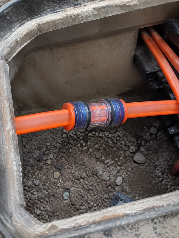
What field teams should verify before blowing fiber through HDPE microduct
Recent guidance and search results place the same controls at the centre of a reliable run: confirm the duct dimensions, keep the sealing zone clean, align the connector, verify full insertion and test the air path using the supplier-approved method. EN 50411-2-8 is a product-specification reference for sealed air-blown-fibre microduct connectors; it does not supply one universal pressure, hold time or reuse rule for every part.
Use the straight connector, reducer connector and gas-block connector pages as separate selection points. Recording which transition was installed makes later leak diagnosis much faster.
FAQ
How do you install the HDPE Microduct without causing an air leak?
Cut the duct square, deburr it, clean the bore and exterior, mark the required insertion depth, and push it fully home in a straight line. Inspect the seal area through a transparent body if available, fit any lock clip and support the duct to prevent side-loading. Pressure-test the completed section before fiber blowing.
What pressure and time should be used to test the HDPE Microduct?
Use the lower of the network’s specified test pressure and the lowest rated component limit, then follow the project’s stabilization and hold period. Record temperature and time with the gauge readings; the correct values vary by system design, connector and network-owner method statement.
Can the HDPE Microduct be reused after the duct is disconnected?
The duct may be reusable if it can be re-cut cleanly and still meets the dimensional and route requirements. A disconnected connector should be reused only when its manufacturer explicitly permits it and inspection confirms an undamaged O-ring, collet and body; otherwise replace the fitting and retest the joint.
Which material and UV rating are best for outdoor HDPE Microduct applications?
Select the duct and connector material against the actual temperature, UV exposure, moisture and mechanical conditions, supported by the supplier’s evidence for the exact SKU. Do not choose by color alone; ask for weathering-test information, material declarations and stated outdoor-service limits.
Why does the HDPE Microduct leak during or after fiber blowing?
Common causes are an out-of-range or oval OD, an angled or burred cut, incomplete insertion, damaged or contaminated O-rings, a wrong straight-versus-reducer choice, or bending load at the fitting. A leak can also appear at temporary test equipment, so isolate and test sections methodically before replacing installed joints.
Do you need tools or lubricant to fit the HDPE Microduct correctly?
Push-fit connectors generally need no tightening tools or lubricant; a suitable tube cutter, cleaning materials and any specified locking clip are normally sufficient. Use only the supplier-approved lubricant if one is specified for the application, because incompatible products can attract dirt or affect seals.
Does EN 50411-2-8 prescribe one field pressure test for every HDPE microduct?
No. It provides a product-specification framework for the covered connector type. The supplier’s exact installation instruction and the project’s acceptance procedure determine the applicable test conditions.
What is the first check when a microduct leaks during fiber blowing?
Check the measured duct size, square cut, cleanliness, insertion depth, connector alignment, locking feature and visible seal condition before changing the compressor setting. Then repeat the approved leak or pressure check.
References
- BS EN 50411 fibre management systems and protective housingsBSI series page; connector and fibre-management scope.
- ITU-T L.156: Air-assisted installation of optical fibre cablesOfficial ITU publication page; blowing-method context.
- IEC Webstore: IEC 60794-5 microduct systemsIEC search page; verify the applicable edition for the cable system.
Reliable fiber blowing begins before the compressor starts: measure the duct, protect the seal and prove the air path. When your team is ready to compare fitting geometry or document a standard assembly, review the Microduct Connectors range and contact Oulu / ANMASPC for product drawings and sourcing support.


