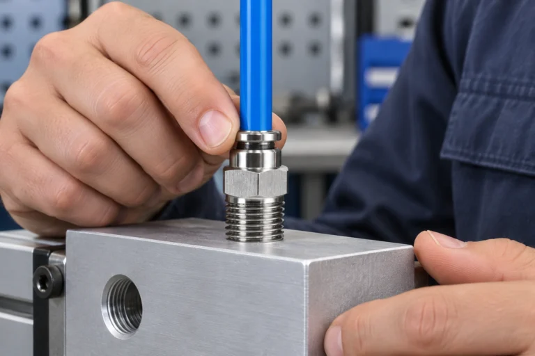
유지보수 기술자가 자동 공기 공급 라인에서 윙윙거리는 직선 커넥터를 발견하면, 조임 조치를 강하게 하는 것은 이해할 수 있는 첫 번째 조치입니다. 또한 이것이 바로 다음 근무 변경 시 동일한 누출 현상이 재발하는 이유이기도 합니다. 직각 피팅은 정상적으로 작동할 수 있지만, 관 직경, 나사 형태, 절단 방식, 삽입 깊이, 실링, 라우팅 또는 교체 부품이 잘못된 경우에 문제가 발생할 수 있습니다. 눈에 보이는 증상은 공기 손실이며, 근본적인 원인은 종종 문서화되지 않은 인터페이스 불일치입니다. 이 가이드에서는 스레드 또는 실링 문제와 튜브 준비, 유지, 호환성 문제로 인한 문제를 구분하기 위해 6가지 검사를 사용합니다. 따라서 팀은 연결을 수리하고 선택 이유를 추적할 수 있는 자료를 남길 수 있습니다.
요약: 누출 공압 직선 피팅 검사 전에 연결부는 분리 및 압력을 빼야 하며, 다음 순서로 점검해야 합니다. 나사식 실링, 튜브 절단, 튜브 피팅, 튜브 외경, 진동 및 고정성, 부품 호환성 순서입니다. ISO 4414:2010은 일반적인 공압 시스템 안전 요구 사항을 규정합니다. 이 규정은 모든 부속품을 서로 교환할 수 있도록 하는 것은 아닙니다. BSPP, BSPT 및 NPT 또한 서로 다른 나사 형태 시스템에 속하기 때문에 외관은 씰의 확실성을 보장하지 않습니다. 실제 튜브 및 포트 세부 정보를 기록하고 부품 데이터 시트를 비교하여 원인을 수정하고 승인된 누출 검사 절차에 따라 수리된 관 연결부를 확인합니다.
일반적으로 누출이 발생하는 직관형 피팅을 설명하는 체크는 몇 가지가 있나요?
| 확인 | 검사할 증거 | 시정 조치 |
|---|---|---|
| 1. 나사산 및 실링 | 니트링의 명칭, 크기, 테이퍼, 실리콘 씰 상태 및 포트 손상 | 니트의 표준 규격을 확인하고 문서화된 밀봉 방법을 사용하십시오. 손상된 부품을 교체하십시오. |
| 2. 관절 절단 | 사각 끝, 깨끗한 표면, 스크레치, 흠집 없음 | 압력을 낮추고 승인된 도구를 사용하여 소음 유출구를 절단하고 잔해물을 제거하십시오. |
| 3. 관형 좌석 | 완전 삽입, 안정적인 커팅날 및 진입부에서 눈에 띄는 간격 없음 | 소리관을 지정된 깊이로 다시 삽입하고 허용된 유지 여부 검사를 수행합니다. |
| 4. 튜브 OD | 측정된 외경은 미터 또는 인치 시리즈이며, 승인된 튜브 재질 | 측정된 OD와 튜브 시리즈를 정확한 부품으로 맞추십시오. |
| 5. 진동 및 라우팅 | 측면 부착, 피팅에 가깝게 구부리거나, 지지대가 없는 구간 및 반복적인 움직임 | 튜브를 지원하고 다시 경로를 설정하세요. 잘못된 사이즈를 수정하기 위해 클립에 의존하지 마세요. |
| 6. 호환성 | 몸체, 씰, 매체, 압력, 온도 및 유량 문서화 | 문서화된 튜브 피팅 포트 조합을 사용하고 교체용 부품에 대한 현재 데이터를 요청하세요. |
연결부의 밸브가 딱 맞을 때에도 밸브가 누출되는 것일까요?
A 공압 직선 피팅 공구 연결부가 포트에 맞지 않는 경우 느슨하게 느껴질 수 있습니다. BSPP는 ISO 228-1과 일반적으로 연관된 평행 나사 연결부 규격이며, BSPT는 ISO 7-1의 압력 견고한 나사 연결부 시스템에서 사용됩니다. NPT는 ASME B1.20.1에 따라 규정된 인치 기반의 테이퍼드 스레드 제품군입니다. 유사 직경 또는 부분적인 끼움은 교환 가능성을 보장하지 않습니다. 강제적인 근접 충돌은 배관을 손상시킬 수 있거나 선이 회전할 때에만 분명해지는 나선형 누출 경로를 남길 수 있습니다.
시스템이 고정되어 있고 압력이 낮아진 상태에서, 기존 부품을 제거하기 전에 포트 도면이나 마킹을 확인하십시오. 적합한 스레드 게이지를 사용하여 주요 직경과 피치를 측정하십시오. 관련 부위의 테이퍼를 확인하십시오. 접근 가능한 나사 구멍에서 기존 실런트를 제거할 때는 실런트 표면을 긁지 마십시오. 해당 스레드와 부품에만 지정된 실런트, 와셔 또는 기타 방법을 사용하여 다시 조립하십시오. 스레드 식별용 대체품으로 토크를 추가하지 마십시오. 스레드 규격을 제품 인증으로 취급하지 마십시오.
튜브 끝은 잘 잘라졌고 제대로 고정되었나요?
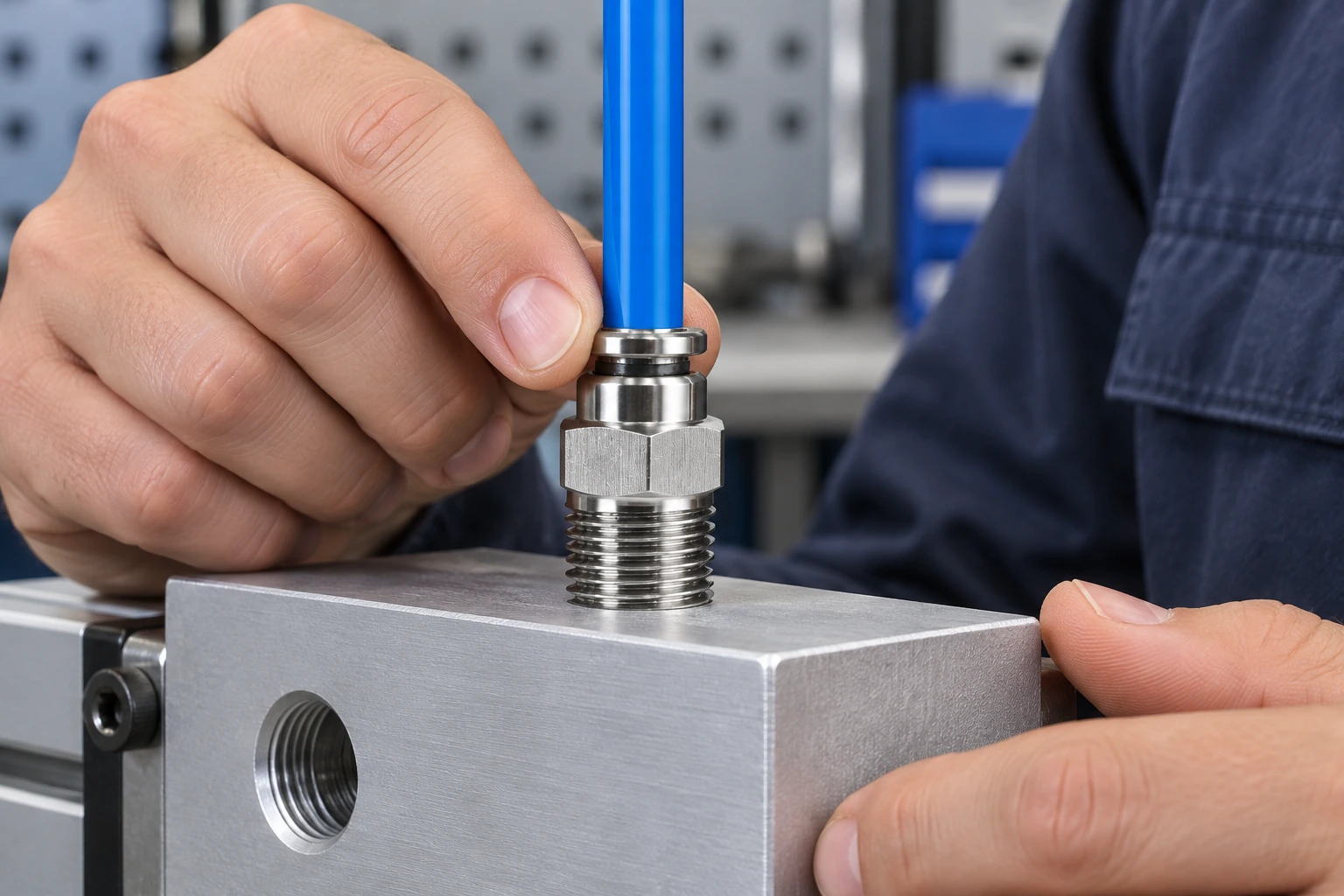
튜브 측의 밀봉은 깨끗하고 정사각형의 끝과 연속적인 표면에 달려 있습니다. 대각선으로 절단되거나, 흠집이 생기거나, 갈라진 부분이나 오염이 생기면, O-링이 누출되는 동안 볼트가 잠시 고정될 수 있을 정도로 그립력을 갖게 될 수 있습니다. 내부 어깨 부분까지 닿지 않는 튜브는 같은 증상을 유발할 수 있습니다. 인서트 방식의 작동은 완전한 착석 상태를 나타내는 증거가 아닙니다.
고립 후에는 해당 튜브 유형에 적합한 도구를 사용하여 손상되지 않은 튜브로 재연결하세요. 새로운 끝 부분을 칩으로부터 깨끗하게 유지하고, 직각으로 그리고 문서에 명시된 깊이까지 삽입한 후, 리브릿 링과 콜렛이 균일하게 움직이는지 확인하십시오. 조립 지침에 풀 체크 또는 누출 체크 방법이 명시되어 있는 경우, 힘 값을 고안하기보다는 해당 방법을 사용하십시오. 압력을 점차적으로 회복시키고 기계의 승인된 절차에 따라 조인트의 상태를 점검하십시오.
외경이 커플링과 일치하는가?
푸시-인 피팅은 단지 명칭 상의 규격만을 기준으로 하여 튜브의 직경을 잡는 것이 아닙니다. 적절한 계측 장치나 계심기를 사용하여 실제 외경을 측정하고 미터법 규격의 튜브와 인치법 규격의 튜브를 구별하십시오. 외관상으로 보기에는 적당한 사이즈라도 누출될 정도로 느슨하거나 올바르게 끼워지지 않을 정도로 크다면 문제가 될 수 있습니다. 피팅 설명서가 조합 범위를 제한할 경우 튜브 소재, 경도 및 허용 오바리티 또한 중요합니다.
교체용 부품을 주문하기 전에 측정된 OD, 튜브 시리즈 및 재질을 기록하세요. 정확한 변형을 위해 부품 도면과 현재 데이터시트를 비교하세요. 수동으로 튜브를 허용하는 커넥터에서 발생하는 경우라도 호환성을 추론하지 마세요. 이 검증 단계는 포트 스레드와 밀봉 방식과 동일한 유지 관리 기록에 포함되어야 합니다. 해당 사이트 공압 부품 유지 관리 가이드 반복적인 서비스 작업에 대한 동반 체크리스트로 사용할 수 있습니다.
진동이나 측면 부하가 적절한 크기의 튜브를 방출할 수 있나요?
예. 올바른 크기의 튜브는 여전히 꺾임부가 피팅에 너무 가깝게 위치하거나 지지대가 없는 구간이 흔들리거나 액추에이터와 매니폴드가 커플링에 밀착될 때 누출이나 방출이 발생할 수 있습니다. 광택이 있는 마찰 흔적, 측면으로 당기는 튜브, 튜브 설명서에서 허용하는 것보다 더 긴 곡률 반경, 구조적 지지대로서 사용되는 피팅 본체 등을 주의 깊게 살펴보십시오. 잠금 클립은 승인된 조립 부품의 고정력을 개선할 수 있지만, 손상된 튜브, 오작동된 직경 또는 완전하지 않은 삽입을 바로잡을 수는 없습니다.
기계가 정지되고 고립된 상태에서 라우팅을 점검하십시오. 설계에 따라 지원을 제공하고, 커넥터의 로딩을 방지하기 위해 이동 중인 부분을 계속 이동시키고, 영구적으로 고정된 튜브가 있거나 긁힘이 있는 튜브를 교체하십시오. 수정 후에는 정적 압력에서만 확인하는 것이 아니라 정상 작동 시에도 유지력과 누출 여부를 확인하십시오. 라우팅 변경 사항을 기록하여 향후 교체 시 동일한 측부 하중이 재현되지 않도록 하십시오.
교체 부품이 전체 공기 경로와 호환됩니까?
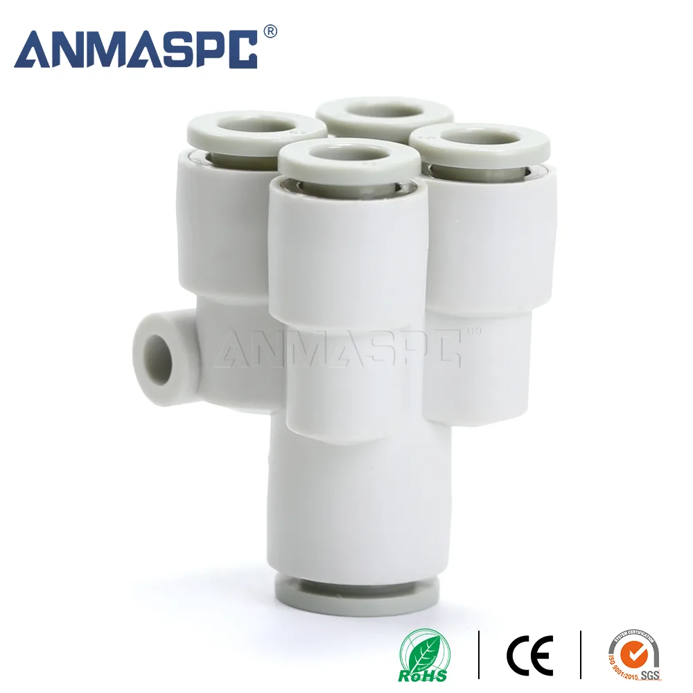
직각 바디는 외관만으로 정의되지 않습니다. 포트 스레드, 튜브 직경, 내부 구멍, 실링 재질, 바디 소재, 매체, 작동 압력 및 온도 범위를 확인하고 승인하기 전에 유량 방향 표식을 확인하십시오. 공압 직선 피팅. 압력 손실은 내부 경로, 상류 및 하류 피팅, 파이프 길이 및 실제 수요에 따라 달라집니다. 나사산 크기만으로는 이를 예측할 수 없습니다. 향상 구성 요소의 경우 화살표 또는 압축 공기 기호에 따르십시오. 평면 직선 커넥터를 사용하려면 공급업체의 문서를 통해 방향이 제한되지 않는지 확인하십시오.
| 연결부 또는 의무 | 유지보수 또는 조달 파일에 기록 | 왜 시각적 일치만으로는 충분하지 않은가 |
|---|---|---|
| 튜브 측면 | 측정된 OD, 미터 또는 인치 시리즈, 재질 및 표면 상태 | Collet grip and seal geometry are dimension-specific |
| Port side | BSPP, BSPT, NPT or other stated thread, size, pitch and sealing method | Look-alike threads may engage without making a pressure-tight joint |
| Operating duty | Medium, working pressure, temperature range, cycling and external exposure | Body and seal suitability depend on the complete envelope |
| Flow path | Required downstream behavior, bore information and any flow data conditions | A restrictive internal path can change actuator response even without an external leak |
| Service method | Isolation point, tube-cutting tool, insertion method and post-repair check | Uncontrolled service can damage a new seal or leave contamination inside the line |
When a replacement is needed, start with the documented 공압 부품 범위 and then request the exact variant’s drawing and limits. The products directory is a catalogue route, not proof that two visually similar parts are interchangeable.
What do ISO standards change about a leak investigation?
ISO 4414:2010 sets general rules and safety requirements for pneumatic fluid-power systems and their components. ISO 12100:2010 provides machinery risk-assessment and risk-reduction principles. They support controlled isolation, documented hazards and safe verification, but neither standard supplies a universal tightening value or certifies a particular fitting. ISO 228-1 and ISO 7-1 describe different BSP-related thread concepts, while ASME B1.20.1 covers general-purpose inch pipe threads such as NPT.
For flow questions, use supplier data or a repeatable method with stated conditions; the U.S. Department of Energy’s compressed-air resources explain why leakage and pressure management should be treated as system issues. Keep the standard edition, part number, tube pairing and inspection result with the repair record. Unsupported claims about pressure, temperature, certification or compatibility can create procurement and safety risk even when the connector appears to work during a brief test.
How should a technician decide between repair and replacement?
- Make the system safe. Follow the machine isolation procedure, shut off the supply and release stored pressure before touching the connector.
- Freeze the evidence. Photograph the installed orientation if permitted, record tube OD and thread marking, and note when the leak appears in the cycle.
- Correct preparation first. Cut back damaged tube, clean the interface and reseat it using the fitting instructions.
- Replace on evidence. Replace the fitting when the body, thread, collet or accessible seal is damaged, when leakage returns after correct preparation, or when the part cannot be identified.
- Verify the assembly. Use the approved leak and functional checks at operating demand, and document the exact replacement and conditions.
For systems that also use controlled air valves, the site’s guide to solenoid valve types helps keep valve direction and fitting interfaces in the same review. A fitting investigation should end with a known interface, not just a quiet hiss at one pressure.
Frequently asked questions about Pneumatic Straight Fittings
Which sealing method is best for the threaded side of the Pneumatic Straight Fittings?
The correct method is the one specified for the identified thread and fitting: it may involve a compatible thread sealant, a washer, or a design that seals elsewhere. Confirm whether the port uses a parallel or tapered thread before applying material, and keep sealant away from the air path. More sealant or more torque cannot compensate for a wrong thread.
How do you measure the Pneumatic Straight Fittings before ordering replacement parts?
Record the tube outside diameter and series, port thread designation and size, fitting orientation, body and seal details, and the operating medium and envelope. Use a drawing or gauge for pitch and taper rather than relying on a ruler or visual comparison. Order against the complete part description and confirm the current datasheet.
What causes a tube to release from the Pneumatic Straight Fittings under vibration?
Common causes include wrong OD, incomplete insertion, a damaged tube end, worn gripping parts, unsupported routing, or side-load from a tight bend. Isolate the system, inspect the tube and collet, correct the routing and use the specified retention check. A clip does not make an unapproved tube-fittings pairing acceptable.
Is plastic, brass or stainless steel better for the Pneumatic Straight Fittings application?
There is no universal material winner. Select the body and seal from the documented medium, pressure, temperature, cleaning, corrosion, mechanical and weight requirements, then verify the exact grade or compound offered for the part. Material alone does not establish a safe operating limit.
How do you check flow direction and airflow loss through the Pneumatic Straight Fittings?
Check the pneumatic symbol, body arrow and supplier documentation to determine whether the component is directional. For airflow loss, compare data measured under stated conditions or measure upstream and downstream pressure at a repeatable operating demand. A static no-flow reading cannot show the pressure loss of a working circuit.
What signs show that the collet or O-ring in the Pneumatic Straight Fittings needs replacement?
Sticking or uneven collet movement, damaged gripping features, a cut or displaced accessible O-ring, recurring leakage after a square cut and correct insertion, or unreliable tube retention are replacement signals. Replace the complete fitting unless the manufacturer identifies a service part and supplies an approved procedure. Do not probe or scratch an accessible seal while investigating.
참고문헌
- ISO 4414:2010, Pneumatic fluid power – General rules and safety requirements for systems and their components.
- ISO 12100:2010, Safety of machinery – General principles for design – Risk assessment and risk reduction.
- U.S. Department of Energy, Industrial Technologies Office, compressed-air systems resources.
- ISO 228-1, Pipe threads where pressure-tight joints are not made on the threads.
- ISO 7-1, Pipe threads where pressure-tight joints are made on the threads.
Leaking 공압 직선 피팅 are best solved by proving the interface in sequence: identify the thread and sealing method, measure the tube OD, inspect the cut and seating, remove vibration loads, and then confirm that the replacement fits the documented pressure, temperature, medium and flow duty. Tightening is only an action, not a diagnosis. The inspection must be performed with the air line isolated and depressurized, and the final check must use the machine’s approved procedure at the relevant operating demand. When the records are complete, Oulu / ANMASPC can support the next sourcing step through its pneumatic parts range and current product documentation. Contact the supplier with the measured interfaces and duty conditions so the selected part can be reviewed as an assembly rather than guessed from appearance.