
When a fiber installer in Oulu, Finland, switched a 12 mm feeder duct to a 10 mm branch, the first pressure check failed within minutes. This is an illustrative scenario, not a claimed customer case: the reversal came after measuring both outside diameters (OD), cleaning the cuts and selecting a reducer matched to each wall thickness. The connector was not “bad”; the transition specification was incomplete.
The short answer is: A reducing microduct connector must match the measured OD and usable insertion length of both ducts. Record OD, inside diameter (ID) and wall thickness, cut square, seat each tube to its visual stop, and leak-test to the project requirement. ISO 4427-2 provides dimensional language for PE pipe, while ISO 3126 covers measurement; neither standard creates a universal pressure rating for every connector. Verify the supplier’s test data for your exact material and application.
What a reducing microduct connector actually does
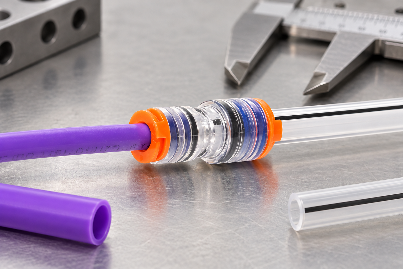
A reducer joins two microducts of different nominal sizes while keeping the air path aligned for blowing fiber. Common search terms include Mini HDPE reducer microduct connectors, HDPE tube reducer connector និង microduct reducer coupler. The fitting normally uses collets or teeth to retain the tube and an elastomer seal to contain air. The body may be clear zinc-alloy or polymer; transparency helps inspection but does not replace a dimensional check.
Nominal labels are only a starting point. Ovalized HDPE, protective sheathing and extrusion tolerances can change the real sealing diameter. Measure at least two points around each tube, note the largest OD, and compare it with the connector’s published range. Measure wall thickness where the tube enters the seal; a heavy-wall tube can have the same OD but a smaller ID, changing blow-friction and mandrel clearance.
Dimension decisions: OD, ID and wall thickness
Use a three-line data sheet for every transition: feeder OD/ID/wall, branch OD/ID/wall, and connector port ranges. ISO 3126’s measurement approach is useful for repeatable dimensional records, while ISO 4427-2 gives PE pipe dimensional concepts; your duct manufacturer’s datasheet remains controlling.
| Measured condition | Recommended decision | Reason |
|---|---|---|
| ODs differ and both fall inside reducer port ranges | Use a reducer coupler | Maintains retention on each side |
| OD matches but wall thickness differs materially | Confirm seal and insertion-depth compatibility | ID and seal compression can change |
| One OD is outside the published range | Stop; select another size or transition piece | Over-compression or pull-out risk |
| Tube is oval, scored or heat-flared | Re-cut to sound material | Seals need a round, smooth surface |
As an illustrative boundary, a 12.0 mm OD tube measured at 12.2 mm after ovalization should not be forced into a port specified only to 12.0 mm. Record the actual reading and ask for written confirmation. Avoid converting a nominal “12/10” label into a universal pressure claim.
Field installation and leak-isolation workflow
- Depressurize and cap the line before cutting. Mark insertion depth with a fine, non-solvent marker.
- Cut both ducts square with a sharp tube cutter; deburr without chamfering away sealing land.
- Wipe dust and blowing lubricant from the first sealing zone. Do not use petroleum lubricant unless the fitting maker permits it.
- Push the larger duct into the matching port, passing the collet until the depth mark reaches the body. Repeat on the smaller side.
- Fit locking clips if supplied. A clip prevents accidental collet release; it does not compensate for wrong OD.
- Pressurize gradually to the project’s approved test value and hold for the specified time. Use a calibrated gauge and document temperature.
If a test fails, isolate one side at a time. Apply approved leak-detection fluid around each seal, then listen for escaping air only after confirming safe pressure. A leak that follows the duct when it is reinserted points to a cut or OD issue; a leak that stays with the connector suggests seal contamination or damage. This workflow avoids replacing sound parts without evidence.
Straight versus reducer transitions
| Transition | Preferred fitting | Inspection focus |
|---|---|---|
| Same OD, same wall family | Straight connector | Equal insertion marks and axial alignment |
| Different OD, compatible seal ranges | Reducing microduct connector | Each port’s OD and depth |
| Different OD plus harsh outdoor exposure | Reducer with documented UV/material data | Body, seal and clip temperature limits |
| Temporary test termination | End stop or cap, not a reducer | Removal plan before cable blowing |
For product context, compare the ឧបករណ៍ភ្ជាប់កាត់បន្ថយមីក្រូឌុយ with the transparent zinc-alloy reducer coupler. A background explanation is available in តើឧបករណ៍ភ្ជាប់មីក្រូឌុយគឺជាអ្វី; use it to align terminology, not as a substitute for a drawing.
Transparent inspection, seals and outdoor evidence
After seating, look through a clear body for a continuous tube end, no visible gap at the seal and a straight air path. Marking both ducts at the body creates a simple movement check during pressure hold. Inspect O-rings for cuts, flattening, swelling or grit. Replace seals after disassembly when the manufacturer treats them as single-use, or whenever damage is visible. Replace the body if threads, collets or windows are cracked.
Outdoor selection requires evidence, not a generic “weatherproof” label. Ask for polymer or alloy grade, UV-exposure method (for example ISO 4892-3 or ASTM G154), and the stated service-temperature range. Temperature cycling can reveal shrinkage at the duct interface; project testing should follow the network owner’s specification. Burial adds soil chemistry and installation-load considerations that a UV test alone does not cover.
Standards, procurement and Oulu/Zhejiang Oulu support
Use ISO 4427-2 for PE pipe dimensional terminology, ISO 3126 for measurement practice, and ISO 4892-3 or ASTM G154 when evaluating accelerated UV exposure. These are references and test methods, not automatic connector certifications. EN 61386-24 may apply to underground conduit systems where specified by the authority having jurisdiction; confirm scope before citing it. Unsupported certification claims can create tender rejection, warranty disputes and traceability gaps.
Procurement checklist: (1) send measured OD/ID/wall data and duct resin; (2) request connector drawings with insertion depth and seal material; (3) agree a project-specific pressure/leak test; (4) define clip, cap and replacement-seal availability; and (5) retain batch and inspection records. Zhejiang Oulu (Oulu) can be considered as a sourcing reference when you need configurable sizes and documentation; evaluate the exact connector against your network specification.
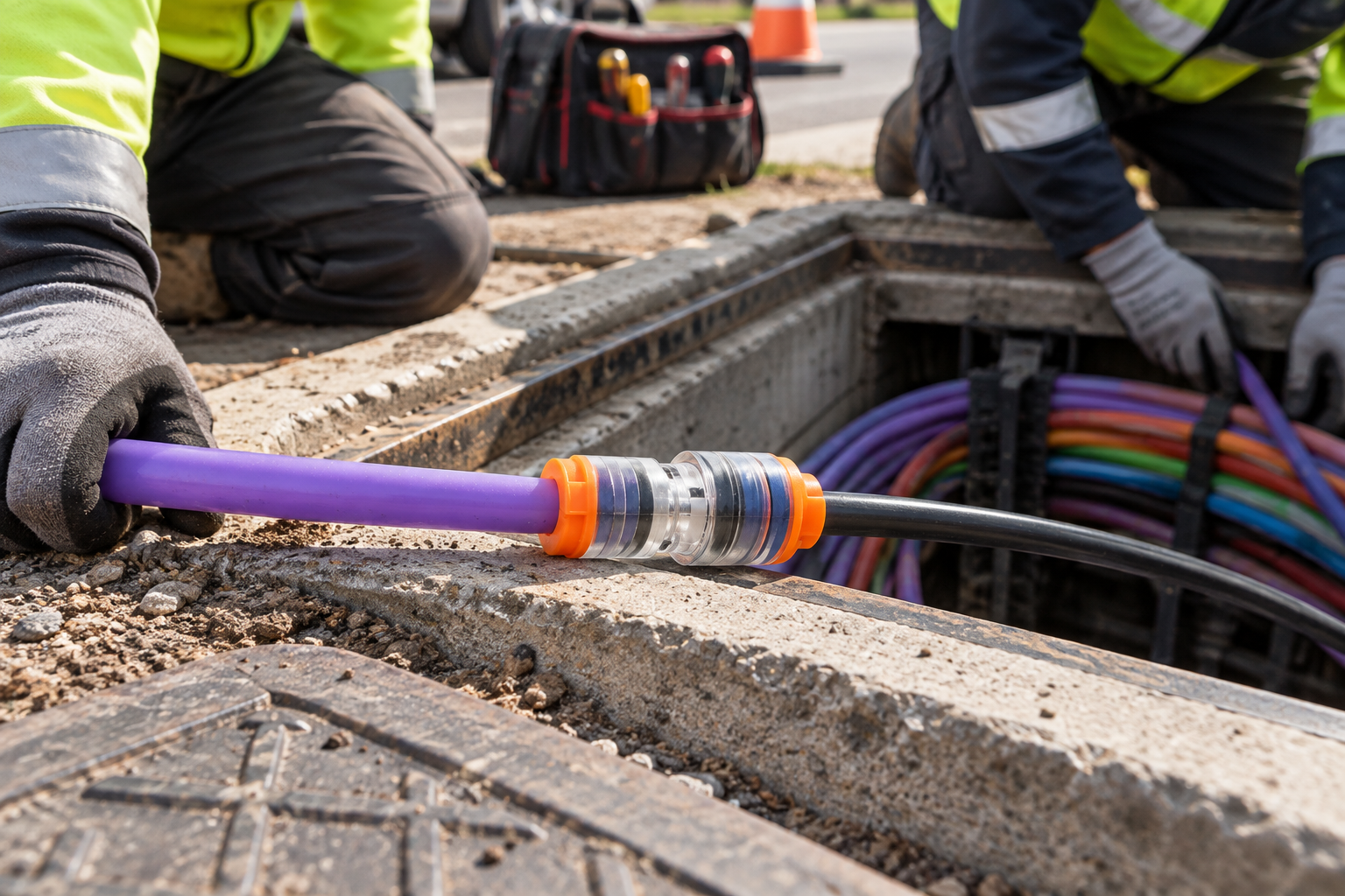
How can installers make a reducing transition auditable?
Photographs are useful, but the strongest handover record combines the image with measurements and test data. Record each duct OD, ID and wall thickness, the connector code, insertion marks, seal inspection, route location and leak-test result. If a future cable pull fails, those fields help the team determine whether the issue is at the transition, the duct or the route.
Review the microduct reducer product page, the connector category and the connector fundamentals article together when preparing installer instructions.
សំណួរដែលសួរញឹកញាប់
Why does the Reducing Microduct Connector leak during or after fiber blowing?
Typical causes are wrong OD, an out-of-square or contaminated cut, incomplete insertion, seal damage or pressure outside the project test plan. Isolate each port, inspect the seal and repeat the test at the approved value before changing components.
Do you need tools or lubricant to fit the Reducing Microduct Connector correctly?
A sharp cutter, depth marker, cleaning cloth and calibrated gauge are normally sufficient. Use lubricant only when the fitting and duct makers approve its chemistry; excess or incompatible lubricant can swell elastomers or attract grit.
How can the Reducing Microduct Connector join ducts with different wall thicknesses?
It can do so when each duct’s measured OD and wall fall within the connector’s separate port ranges and the seal compression is documented. Equal nominal OD alone is not proof of compatibility; confirm the drawing or obtain written engineering approval.
What temperature range should the Reducing Microduct Connector withstand?
Use the supplier’s stated operating and installation limits for the exact body and seal materials. Do not infer a universal range from HDPE resin data; combine temperature cycling, UV and pressure requirements in the project qualification.
How can installers visually check that the Reducing Microduct Connector is fully seated?
Use the body’s inspection window or insertion-depth mark: the tube should pass the collet and stop evenly, with no gap at the seal. Mark both tubes and verify that the marks do not move during the pressure hold.
When should the seals or body of the Reducing Microduct Connector be replaced?
Replace a seal when cut, flattened, swollen, contaminated or removed contrary to the maker’s reuse guidance. Replace the body for cracked windows, damaged threads, bent collets or any retention failure found during inspection.
Which measurement should be written first for a reducing microduct connector?
Write the measured OD for each duct first, then add ID, wall thickness, material and insertion length. That order makes the two-sided transition explicit and reduces the chance of ordering a straight part by mistake.
What evidence is needed before covering a reducing connector?
Keep the dimensional check, cut and seal inspection, insertion confirmation, connector identification, route location and approved leak-test result. Do not rely on a product photo as the only acceptance record.
ឯកសារយោង
- ISO 3126: Plastics piping systems – plastics components – determination of dimensionsOfficial ISO page; dimensional measurement reference.
- ISO 4427-2: Polyethylene pipes and fittings for water supplyOfficial ISO page; PE terminology and dimensions context.
- ASTM F2164: Field leak testing of polyethylene pressure pipingOfficial ASTM page; field test method reference.
Measure first, seat visibly, test by the project specification, and document the transition. When you are ready to review sizes, see the microduct connector range and contact the team for a drawing-based recommendation.


