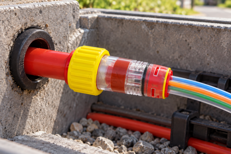
When a commissioning technician in Bristol pressurized a new microduct section, the gauge fell rapidly and the team blamed the gas-block fitting. Replacing it changed nothing. A review found that the seal had been tightened before cable blowing and the jacket carried a shallow groove at the sealing point: the failed test exposed a process error rather than an unexplained product defect.
សេចក្តីសង្ខេប៖ Pressure-test an HDPE block microduct connector only after confirming duct OD, cable range, seal activation, route restraints, and the rating of every component. Record medium, pressure, temperature, stabilization, hold time, allowed decay, and result. The referenced product page lists 0.8 MPa air tightness, 2.5 MPa proof pressure, and a 0–1.6 MPa operating range; use 16 bar only as an exact-product verification checkpoint, never as a universal connector rating.
Define the acceptance question before connecting the pressure gauge
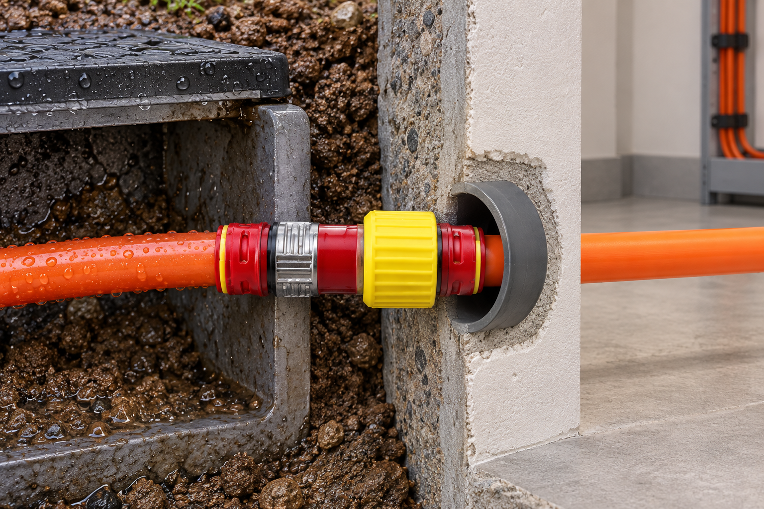
“Pressure tested” is not an acceptance criterion. The method statement should identify the test purpose, medium, target, ramp rate, stabilization period, hold duration, permissible decay, temperature correction, leak-location method, exclusion zone, and authority to approve. A blowing-pressure check, working-pressure test, proof test, and water-migration test answer different questions.
Set the limit from the lowest-rated item: duct, connector, cable seal, stop end, hose, valve, or gauge. Verify whether figures mean temporary blowing, continuous service, or proof testing. ITU-T L.79 treats microduct blowing as a system, the right perspective for pressure safety.
Choose the method for the failure mode. An air hold can reveal small gas leakage efficiently, but it does not by itself prove that liquid water will or will not pass under a specified head; conversely, no visible water passage does not prove gas tightness. Where the entry must control both, define separate acceptance conditions or cite a validated combined method. Keep supplier ratings, project acceptance pressure, and safe field test pressure as three distinct entries.
Prepare both the duct seal and cable-annulus seal for the final test state
Confirm the exact code and inspect packaging or traceability before use. Measure clean duct OD in two axes; obtain its ID and wall thickness; and compare the cable’s minimum and maximum jacket OD with the seal range. Hdpe Gas And Water Block Straight Fittings require both interfaces to be correct. A nominal duct size alone cannot validate the cable seal.
Cut the tube square, remove loose burrs, clean the OD, mark insertion depth, and push it axially to the reference. Keep the annular seal relaxed during cable blowing unless verified instructions say otherwise. After cable placement, inspect the jacket, activate the seal to the defined torque, travel, or stop, fit any required locking feature, and support the route so the connector carries no avoidable bending load.
Use a staged release: first confirm “open for blowing,” then “cable accepted,” and finally “activated for pressure test.” The test record must state the last completed stage and the exact connector assembly code. Otherwise, a stable pressure result may be wrongly attached to a different seal state, cable range, or part revision during handover.
ទី push-fit connector size and pressure guide can assist early selection. For commissioning, rely on the exact drawing, installation instructions, and approved project test method.
| Test type | Primary purpose | Typical timing | Key evidence | Do not confuse with |
|---|---|---|---|---|
| Low-pressure leak check | Locate gross assembly leakage | Before full acceptance test | Stable setup and interface inspection | Proof of rated working pressure |
| Blowing-pressure verification | Confirm safe installation operation | During route preparation | System limit and monitored pressure | Continuous-service rating |
| Working-pressure hold | Verify assembled route at specified service condition | After seal activation | Calibrated record, time, temperature | Proof or burst test |
| Proof test | Demonstrate margin under a defined method | Supplier or controlled project test | Procedure, sample state, acceptance | Permission to operate continuously at proof pressure |
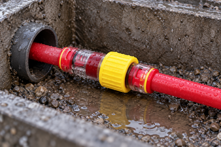
| Water-migration test | Check liquid pathway under defined exposure | Qualification or site acceptance | Head/pressure, duration, orientation | Air-pressure decay alone |
Use 16 bar only after every component and test condition is verified
The gas-block product page identifies an operating range up to 1.6 MPa, equal to 16 bar, for the published family. Before putting 16 bar on a field schedule, obtain confirmation for the selected size, revision, cable range, test medium, temperature, duration, and assembly. Confirm that the duct and all accessories also allow it. If any evidence is missing, lower the test to the approved system limit or stop until the design authority resolves the gap.
Restrain end closures mechanically, use a regulator and relief device, keep people out of the line of fire, and increase pressure in controlled stages. Pause for inspection before the target. Allow temperature and material strain to stabilize; then start the timed hold. Record calibrated gauge identity, initial and final pressure, ambient and medium temperature, duration, and observations. Depressurize through a controlled outlet before touching the assembly.
Do not start the hold clock while pressure and temperature are still settling. Compression heating, cooling, sunlight, and duct expansion can move the gauge even when the assembly is sound. Record the stabilization interval separately, then capture medium, temperatures, hold time, initial and final pressure, permitted change, assembly code and seal state. If the approved procedure provides no temperature correction, wait for stable conditions rather than inventing one.
If leakage appears, use an approved detection method at each interface. Soap solution can help locate an air leak when compatible, but it cannot validate water or a particular gas claim. Do not tighten a live fitting. Isolate and depressurize, then inspect the tube cut, insertion depth, O-rings, cable range, seal orientation, activation setting, body, locking parts, and side load.
| Checklist item | Required entry | Pass indicator | Escalation trigger |
|---|---|---|---|
| Component limits | Working/proof values and sources | Test below every approved limit | Ambiguous units or rating type |
| Dimensions | Duct OD/ID and cable min/max OD | All within exact code ranges | Nominal-only or borderline fit |
| Assembly | Insertion, activation, clip, support | Visual marks and hold point complete | Seal tightened before blowing |
| Instrumentation | Gauge ID, range, calibration status | Suitable resolution and in date | No traceable calibration |
| លក្ខខណ្ឌសាកល្បង | Medium, pressure, time, temperature | Match approved method | Unapproved 16 bar assumption |
| Outcome | Decay, visible leaks, corrective action | Within acceptance criteria | Repeat failure or body damage |
Diagnose one failure mechanism at a time before retesting the route
The highest-frequency mistakes are wrong duct or cable size, incomplete insertion, angled cuts, grit on the seal, incompatible lubricant, premature seal tightening, an unrestrained end stop, an unsuitable gauge, ignored temperature change, and undocumented acceptance limits. A microduct straight gas-tight block connector cannot compensate for a damaged cable jacket or a wall penetration left unsealed.
After a failure, correct one identified cause at a time and record what changed. Replace O-rings or cable seals that are cut, flattened, swollen, hardened, or contaminated. Replace cracked, crazed, distorted, or grip-deficient bodies. Recut the tube only if the route has enough length and the resulting end remains within geometry limits. Then repeat the complete test rather than only checking the previously leaking point.
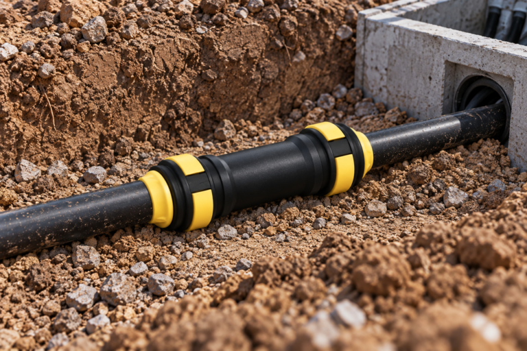
For closure-selection context, use the site’s end-stop versus gas-block guide. An end closure for an empty duct and a gas block around an installed cable have different duties and test states.
Apply destination-specific safety, access, and evidence requirements
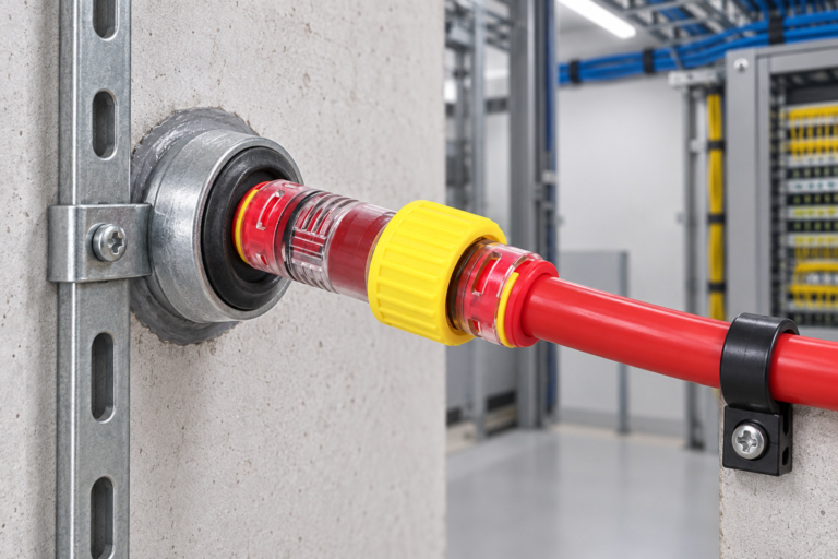
In the UK, follow the network owner’s engineering instructions, site rules, street-works controls, and any physical-infrastructure access conditions. Ofcom’s access framework governs market access obligations; it is not technical approval for a connector. European projects likewise need destination-specific operator, building, safety, and environmental requirements.
Outdoor qualification should state temperature range and UV evidence. ISO 4892-3 defines fluorescent-UV exposure for plastics, while IEC 60529 defines IP-code testing. Both are test frameworks, not automatic certifications or warranties for an installed route. Commercial documents should say what was tested, for how long, in which configuration, and against which pass criterion.
Link selection, installation, and test records to the exact route section
- Separate blowing, working, proof, and ingress requirements in the specification.
- Approve the exact duct-cable-connector combination with production tolerances.
- Place seal activation after cable installation and make it a signed hold point.
- Use calibrated equipment, controlled restraints, and an approved exclusion zone.
- Link test results, corrective action, and retest to the route and component codes.
Zhejiang Oulu publishes dimensional and pressure data for gas-block connector families. Use this as supplier input, then obtain code-specific confirmation and test documentation before adopting any value in an installation or tender schedule.
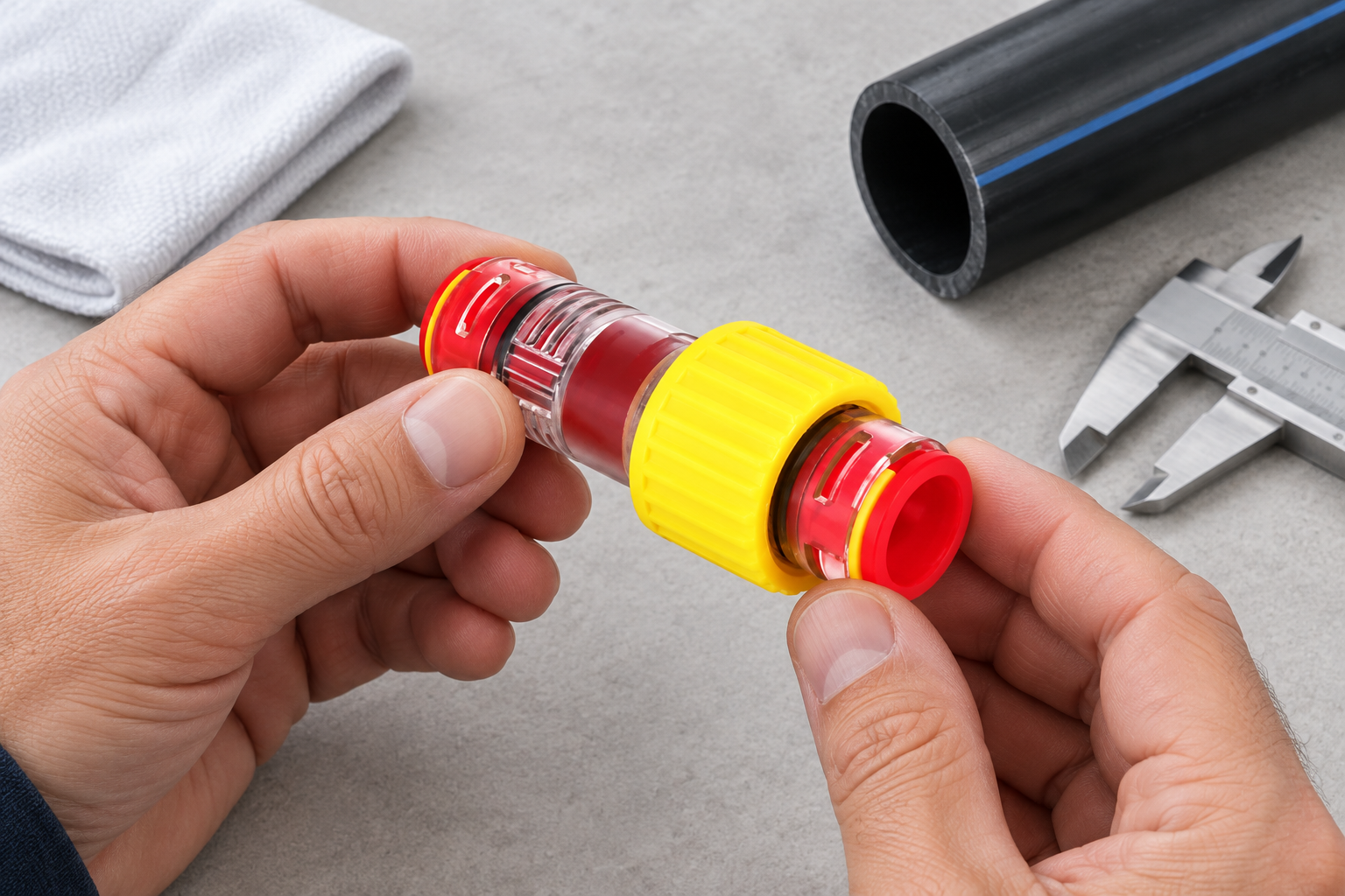
Questions installers ask before signing the pressure-test record
How do you install a HDPE block microduct connector at a building entry point?
Support and prepare the duct, seat the exact connector, install the compatible cable, activate its seal, and pressure-test. Seal the wall penetration separately with the approved building-entry or fire system.
What pressure rating is suitable for a HDPE block microduct connector in an outside-plant network?
Use a verified working rating above defined operating and installation pressures with the required design margin. The lowest-rated route component governs, and proof pressure is not continuous working pressure.
How can you test a HDPE block microduct connector for air, gas and water leakage?
Use a medium-specific approved procedure stating pressure or head, ramp, stabilization, hold time, temperature, and acceptance criteria. Test particular gases or water separately where air decay does not represent the claimed performance.
Can a HDPE block microduct connector be reopened for cable maintenance?
Yes only when the product is designed and instructed for release. Depressurize, remove locking parts, release without twisting the cable, replace damaged seals, and perform full recommissioning.
Which duct sizes and cable diameters are compatible with a HDPE block microduct connector?
Compatibility is defined by the exact part code’s duct-OD and cable-diameter ranges. Measure both and check production tolerances; nominal size or duct ID alone is insufficient.
What happens if the seal is tightened before cable blowing?
It can restrict the bore, increase drag, mark the jacket, move the fitting, or stop installation. Release and inspect the seal and cable according to instructions before continuing.
Use these sources to verify the pressure-test and field-control plan
- IEC 60529, Degrees of protection provided by enclosures (IP Code)
- ISO 4892-3, Plastics—Methods of exposure to laboratory light sources
- ITU-T L.79, Optical fibre cable elements for microduct blowing installation
- Ofcom, Physical infrastructure access
The pressure number matters only when the component, configuration, method, and acceptance record all agree.
Review the published ranges for the Gas Block Connector For Micro Duct End, then contact Oulu with exact duct and cable dimensions, route pressures, medium, hold time, and required documentation.