
When a network installer in Bristol encountered an unexpectedly weak signal after a new fiber run, the first suspect was a faulty cable. In this illustrative acceptance-test scenario, a quick inspection instead revealed a sharply bent section near a duct entry. Replacing the cable without correcting the route would miss the real issue: optical performance depends on the fiber choice, pathway and installation process together.
まとめ: Fiber optic communication encodes information onto light and guides it along an optical fiber; receivers convert the arriving signal back into electrical data. Single-mode and multimode are distinct design choices, not grades of the same interchangeable cable: ITU-T G.652 addresses single-mode fiber, while ITU-T G.651.1 covers 50/125 µm graded-index multimode fiber. Select against the equipment and distance plan, then document the link-loss budget and test the installed route rather than relying on the cable label alone.
How Transmitters, Fibers, and Receivers Carry Data
A transmitter varies a light source in a pattern that represents data. The light travels in the fiber’s core, whose refractive index is higher than that of the surrounding cladding; within the fiber’s permitted angles, total internal reflection helps confine the light. At the far end, an optical receiver detects the signal. The protective coating and cable construction serve mechanical and environmental needs, but they are not the light-guiding core.
This explanation is useful, but it does not mean every launched ray travels without loss. Absorption, scattering, macrobends, microbends, splices and connector interfaces can reduce the signal reaching the receiver. The Fiber Optic Association (FOA) technical reference distinguishes fiber attenuation from connection and installation losses. A link budget accounts for all of them, with the applicable transceiver specifications supplying the permissible end-to-end limit.
Optical fiber is also only one part of a communications system. Transmitters, receivers, connectors, splice points and the route must work as a matched design. For a broader comparison of the transmission medium with metallic cabling, see why fiber optic transmission is used; its benefits still depend on the application’s equipment and installation.
Match Fiber Mode to Equipment and Distance
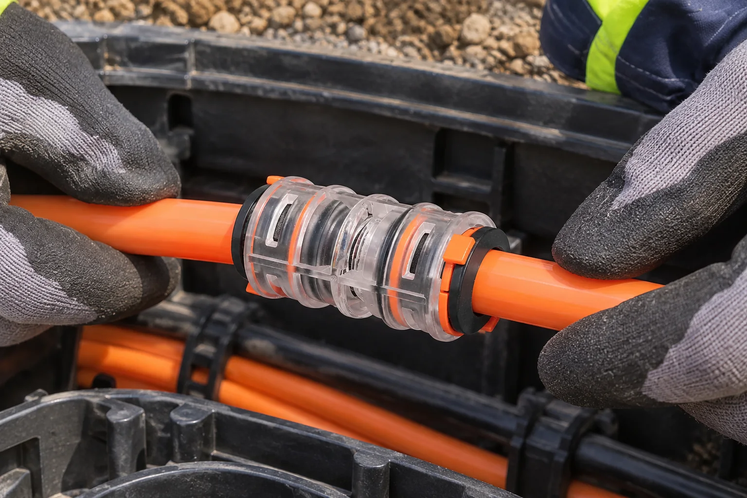
Single-mode fiber supports one principal propagation mode and is commonly selected for longer telecommunications routes; multimode fiber allows multiple modes and is used in links whose reach and equipment plan fit its characteristics. Mode choice is not a claim that one cable will automatically be faster. The transmitter wavelength, transceiver type, fiber specification, connector and required reach must all agree. ITU-T G.652 describes characteristics of single-mode optical fiber and cable, while ITU-T G.651.1 covers 50/125 µm graded-index multimode fiber and cable for optical access networks.
Do not infer connector compatibility from an outside cable diameter or a familiar plug shape. Record the fiber type, connector interface, polish where relevant, equipment wavelength and approved link distance from the actual equipment documentation. If existing infrastructure is involved, identify the installed fiber by records and appropriate field verification before purchasing optics. The future trends in optical communication matter less to today’s bill of materials than these interfaces and a realistic upgrade path.
| 決定点 | Single-mode | Multimode |
|---|---|---|
| Light propagation | One principal mode; G.652 is a relevant telecommunications fiber reference. | Multiple modes; G.651.1 addresses 50/125 µm graded-index fiber for optical access networks. |
| Reach and equipment | Check the selected optics, wavelength and complete loss budget for the actual route. | Check the specific multimode grade, optics and published reach; modal dispersion can limit a link. |
| Installed-base fit | Verify fiber records, connector condition and transceiver compatibility. | Verify fiber grade and continuity; the word “multimode” alone is insufficient. |
| Cost tendency | Compare transceivers, cable, termination and testing as a system, not just fiber price. | Compare the same complete scope; equipment and reach can reverse a simple material-price assumption. |
Calculate the Link-Loss Budget and Test the Installed Fiber
Begin with the receiver sensitivity and transmitter output specified for the chosen optics, then account for fiber attenuation over the route length, planned splices, connector pairs and a project-defined reserve. For an illustrative estimate, planned loss = fiber attenuation + splice losses + connector losses + engineering margin; the component values must come from the selected products and project acceptance criteria. There is no universal acceptable loss figure for every link.
After installation, use a calibrated optical loss test set at the wavelengths and reference method specified for the project to measure end-to-end insertion loss. An optical time-domain reflectometer (OTDR) can help locate events and characterize the route, but its trace is not a substitute for the agreed end-to-end loss measurement. FOA’s testing references explain the different purposes of these methods. Keep test records tied to the fiber identifiers and the as-built route so a later repair crew can distinguish a new fault from a pre-existing condition.
The same budget should guide physical work. Keep the manufacturer’s minimum bend radius and pulling or blowing limits visible to the crew; protect open ends from dirt and moisture; inspect and clean mating optical connectors using the approved procedure before connection. For an air-blown system, verify the duct’s bore, continuity, bends and joints against the fiber unit and equipment instructions. A good fiber specification cannot compensate for a crushed duct or a contaminated interface.
Compare the Complete Installed Route Before Buying
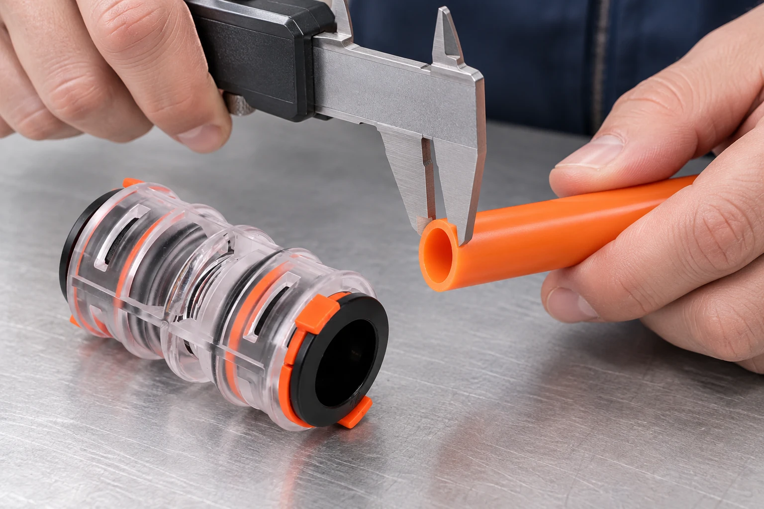
Fiber optic technology advantages often include high capacity, long-reach options and immunity of the glass signal path to electromagnetic interference. These are system-level possibilities, not guarantees for every route or a certification of the cable. Procurement should compare the complete installed link: compatible optics, fiber and cable, pathway, fittings, termination, tests, documentation and the cost of gaining access for future changes.
A low cable quote can become expensive if interfaces have to be reworked or the route must be reopened. Conversely, spare pathway capacity has value only when it is recorded, accessible and kept suitable for later use. Model the present installation and a plausible expansion scenario over the same planning period; label future demand and crew costs as assumptions. Do not claim a payback period until those inputs are known.
| Project condition | 要求する証拠 | Decision it supports |
|---|---|---|
| Known equipment at both ends | Optics data, wavelength, supported fiber type and allowable loss. | Choose compatible fiber and calculate the route-specific budget. |
| Existing fiber route | As-built records, fiber identification, connector condition and field test results. | Decide whether reuse is feasible before ordering replacement components. |
| New microduct route | Duct and fiber-unit dimensions, bend plan, joint details and installation instructions. | Check physical fit and installation method before selecting fittings. |
| Phased expansion | Demand scenarios, spare usable pathway, access points and future mobilization estimate. | Compare whole-life options without assuming spare capacity is free. |
| Acceptance and maintenance | Loss-test method, wavelengths, limits, fiber IDs and as-built deliverables. | Make acceptance repeatable and future fault isolation faster. |
Match Each Fiber Standard to Its Stated Scope
ITU-T G.652 defines characteristics for a single-mode optical fiber and cable; ITU-T G.651.1 defines characteristics for 50/125 µm graded-index multimode optical fiber and cable for optical access networks. They help specify fiber, not certify a completed link, a microduct fitting or a contractor’s workmanship. FOA technical references are educational guidance on fiber, installation and testing, not a product approval. Contracts should name the exact standard edition, fiber variant, equipment requirements and field acceptance method that apply.
Compliance claims must also match the destination market, intended application and evidence supplied. Ask for the selected product’s datasheet and applicable test documentation instead of accepting a blanket “standards compliant” label. Unsupported claims can result in a rejected submittal, procurement delay or costly replacement even when the components physically fit.
Define Equipment, Fiber, Pathway, and Test Interfaces Before Requesting Quotes
- State the service, route length, equipment at both ends and expected growth; get the transceiver makers’ supported fiber and link limits.
- Identify the fiber type and cable construction, then calculate the loss budget from actual route and component data.
- Draw the pathway, bends, access points, joints and terminations; confirm duct-to-cable or duct-to-fiber-unit fit from both manufacturers.
- Set an installation method and an acceptance plan with wavelengths, test method, thresholds and deliverable records before work starts.
- Compare complete installed and future-access costs, including any spare pathway, rather than choosing on cable unit price.
Microduct Connector can help buyers review the fitting and pathway side of a fiber route against the documented duct dimensions and application. For access-network context, see fiber-to-the-home microduct design. Optical fiber and microduct fittings perform different jobs, so confirm each interface independently.
よくある質問
How does fiber optic communication work?
A transmitter encodes data into light, the optical fiber guides the signal, and a receiver converts it back to electrical data. Core and cladding refractive indices help guide light through total internal reflection. The usable link still depends on attenuation, connections, bends and the chosen optics.
What is the difference between single-mode and multimode fiber?
Single-mode supports one principal propagation mode; multimode supports multiple modes. ITU-T G.652 and G.651.1 address different fiber types, but the correct choice also depends on transceivers, wavelength, reach and installed infrastructure. Do not mix them based on connector appearance alone.
Does optical fiber lose signal over distance?
Yes. The glass has attenuation, and splices, connectors and bends can add loss. Calculate the budget for the specific link, then measure the installed link using the project’s stated wavelengths and reference method.
Is optical fiber immune to every type of interference?
The optical signal in glass is not carried as an electrical current, so electromagnetic interference does not affect it in the way it affects a metallic signal path. That does not make the whole system immune to power, equipment, grounding or physical-installation problems. Assess those separately.
Can single-mode fiber be installed in any microduct?
No. Fiber type does not establish cable outer diameter, duct clearance or installation suitability. Check the actual cable or fiber unit, duct bore, route geometry, fittings and installation-equipment instructions together.
Which test confirms a newly installed fiber link?
An optical loss test set measures end-to-end insertion loss against the agreed budget at specified wavelengths. An OTDR helps characterize and locate events, but it answers a different question. Record the method, limits and results against each fiber identifier.
参考文献
- ITU-T G.652, Characteristics of a single-mode optical fibre and cable.
- ITU-T G.651.1, Characteristics of a 50/125 µm multimode graded index optical fibre cable for the optical access network.
- Fiber Optic Association, Online Reference Guide to Fiber Optics.
The practical rule: specify the signal path and the physical pathway as one documented system, then test what was built. Review マイクロダクトコネクタ against your duct and installation requirements, and contact the Microduct Connector team with the route drawing and component specifications to discuss a suitable fitting.


