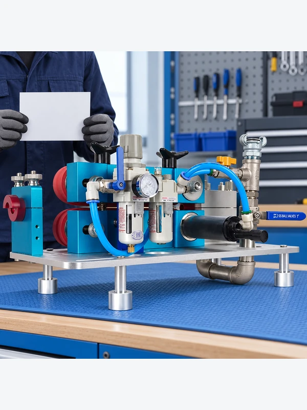
When comparing fiber-blowing machines for a European FTTH project, check the conditions behind each stated speed and installation distance. A machine is useful only when its approved cable range, duct range, propulsion method, control window, safety provisions and service plan match the route. Ask the supplier to demonstrate installation of the specified cable through a prepared microduct, with settings and stoppages recorded.
Compare a hydraulic or pneumatic cable-blowing machine as part of a cable–duct–route system. Request the exact operating envelope, setup procedure, safety documentation, test basis, spare-parts plan and service coverage. Do not transfer a product-page speed or distance to a different cable, duct, bend profile or weather condition without qualification.
How a fiber-blowing machine controls cable feed and air assistance
Depending on the design, the machine controls cable feed, traction, air-assisted movement or a combination of these functions. The crew still needs a continuous duct, compatible cable surface, suitable bends, controlled air supply and a safe stopping method. The machine cannot correct a crushed duct, a leaking connector, an obstructed chamber or a cable outside the approved range.
| Comparison area | Question for the supplier | 要求する証拠 |
|---|---|---|
| Cable and duct fit | Which cable diameters, duct IDs, surfaces and bend conditions are approved? | Operating envelope and route qualification notes |
| Control | How are feed force, air flow, speed and stopping controlled? | Controls description and setup procedure |
| Safety | How are stored energy, guarding and emergency stops managed? | Manual, risk information and training material |
| サービス | What calibration, wear parts and response support are available? | Maintenance schedule and spare-parts list |
How do hydraulic and pneumatic propulsion approaches differ?
Hydraulic actuation can provide controlled mechanical force; pneumatic systems use compressed air to propel or assist the cable. Neither approach is automatically safer or more efficient. Risk and output depend on guarding, stored energy, route preparation, operator training, settings and the exact cable and duct combination.
| Project question | Hydraulic emphasis | Pneumatic emphasis |
|---|---|---|
| Force control | Specify pressure, traction and relief controls | Specify air pressure, flow and feed coordination |
| Route preparation | Check alignment, feed path and cable surface | Check duct sealing, airflow path and joint leakage |
| Field records | Record force/settings and interventions | Record air settings, hold checks and interventions |
| Decision boundary | Use only within the approved cable and duct limits | Do not infer performance from compressor capacity alone |
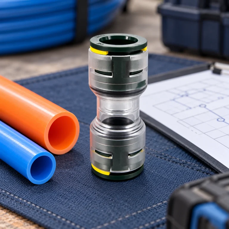
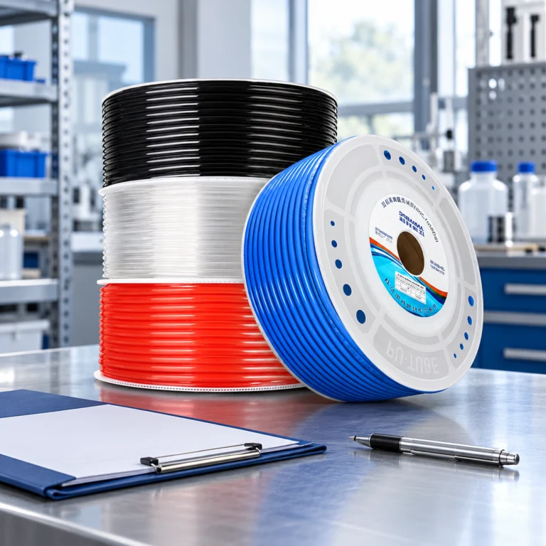
The cable blowing machine range should be reviewed alongside the HDPE microduct specifications and straight connector specifications. A complete system check is more informative than a machine-only comparison.
Compare both machines on a controlled test route
A fair machine comparison needs a common test plan before either supplier begins. Identify the cable manufacturer and construction, OD, duct system and bore, route length, bends, elevation, joins and access points. Agree the permitted lubricant, cable handling, drum arrangement and operating limits. If one machine is tested on a shorter or cleaner route, the result is a comparison of two installations rather than an isolated comparison of machine capability.
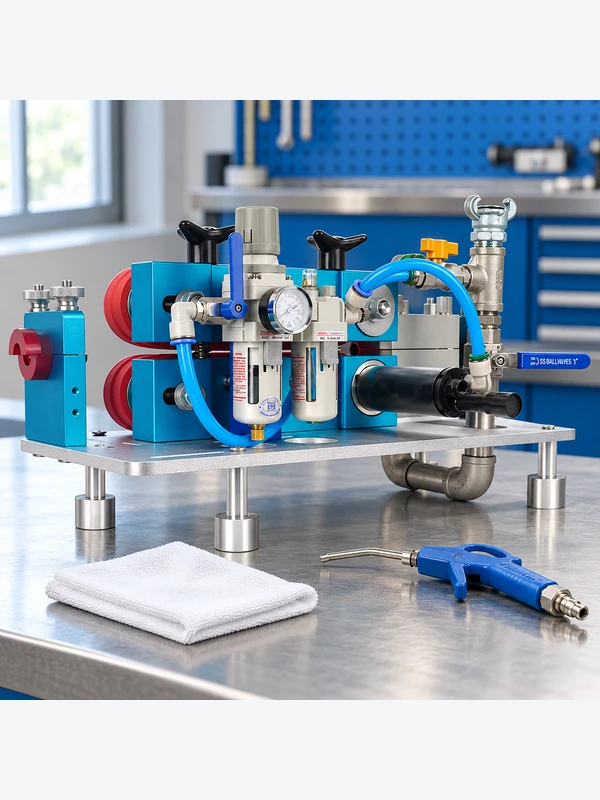
Record utilities under the actual test conditions. A compressor’s advertised maximum pressure does not identify delivered airflow at the machine during the run. Document the compressor, treatment equipment, hose arrangement and relevant operating readings using the approved instrumentation. Distinguish the machine’s cable-drive power from air assistance in the duct. Both hydraulic-drive and pneumatic-drive configurations need a clear account of the energy sources actually supplied.
Agree a comparable test endpoint. Griffioen and Jonker’s IWCS 2021 abstract, published by Plumettaz, discusses how bend-only trajectories and speed resonances can affect blowing tests and recommends consistent end conditions. Its illustrative pressure and speed settings are not universal operating instructions. Apply the lesson about comparability while staying within the cable, duct and machine manufacturers’ approved limits for the tested configuration.
Measure accepted installation output with its qualifications: distance completed, time definition, speed record where available, interventions, stops and any observed cable damage. Record which values are measured automatically, measured manually or not measured. Include setup and recovery time separately from uninterrupted feed time. When a supplier cannot export a parameter, agree a manual record rather than treating a dashboard or headline figure as equivalent evidence.
Check the duct route before sending the installation crew
Verify duct continuity, section length, bends, chamber access, water, obstruction, cable compatibility and joint condition. Inspect every accessible connector for a square cut and full insertion. Qualify a representative cable–duct section using the documented method before releasing production quantities. During the run, log the machine, cable, duct section, settings, start/stop points and any intervention.
Use repair and installation records to compare operating costs
Public connectivity reporting, including the European Commission’s State of the Digital Decade report, describes the continuing importance of fiber-based access. For equipment buyers planning this work, compare documented installations across the contractors and route conditions involved. Fewer repeat visits, maintainable equipment, controlled cable handling and future-accessible pathways are reasonable procurement questions, but they should be supported by project evidence.
Investigate a stoppage before changing the drive settings
A stop is an event to diagnose, not permission to increase force or pressure until the cable moves. Follow the machine’s stop, isolation and stored-energy procedures. Note cable distance, route section, available operating readings and the events immediately before the stop. Keep personnel clear of discharge points and moving equipment. The machine’s manual and project method statement determine the permitted recovery sequence.
Check whether the event points to the pathway, cable handling or equipment. A blockage, water, an unintended bore transition, a leaking joint or drum resistance can change the result without a drive defect. Inspect the safely accessible route and review the cable–duct pairing before another attempt. The connector documentation article explains why joint locations and dimensions belong in the route record rather than in an unrelated materials file.
If a physical condition is corrected, identify what changed before comparing the restart with the first run. Replacing a cable, altering a bend, changing lubricant or substituting a compressor may require a revised acceptance trial. Do not combine the best segment from several differently configured runs into one unexplained performance claim. Keep failed or interrupted runs in the record, along with the stated reason for exclusion if a contractual comparison omits them.
For purchasing, compare total time and support exposure as well as completed distance. A candidate that needs different utilities, specialised wear parts or a service visit has a different ownership requirement. Ask for the applicable maintenance schedule, available spares and the method used to confirm settings. The machine range can identify candidates, while the HDPE microduct specifications and project route establish the boundaries of a meaningful trial.
What to include in a fiber-blowing machine quotation
Ask for a dimensional drawing, approved cable and duct ranges, control limits, safety documentation, test conditions, noise or emissions information where relevant, maintenance intervals, wear parts, training, commissioning support and service response. Treat claims such as “high speed,” “long distance” or “universal” as incomplete until the conditions are stated.
Check compressed-air requirements on hydraulic-drive machines
Identify the cable-feed drive and the air supply to the duct separately. A machine with a hydraulic drive may still use compressed air for cable installation; the supplier must identify the configuration actually offered. Compare its cable feed control, approved pressure limits, connections, guarding and stop procedure rather than assuming the drive label describes every energy source.
As one manufacturer-specific example, Plumettaz’s IntelliBox lists monitoring of pushing force and belt slippage, stopping at preset limits, and recording installation parameters. This supports asking suppliers which variables their offered system measures and controls. It does not establish that every blowing machine has these functions or that another supplier’s machine provides equivalent protection.
Which EU machinery rules apply to a 2026 or 2027 purchase?
Use the date the equipment is first placed on the EU market to determine the applicable machinery rules. The European Commission’s machinery guidance, checked on 7 October 2026, states that machinery placed on the market before 20 January 2027 must comply with Directive 2006/42/EC; Regulation (EU) 2023/1230 applies mandatorily from 20 January 2027. Confirm the applicable scope and conformity route for the specific machine and supplied assembly.
Request model-specific conformity documentation, instructions and the supplier’s explanation of applicable legislation. The Commission warns that additional voluntary certificates are not a recognised substitute for the required conformity procedure. Do not treat a certificate image, an EU sales address or a generic CE claim as proof that the offered configuration is compliant or suitable for the route. Resolve country-specific or classification questions with the relevant authority.
よくある質問
Is pneumatic propulsion automatically safer than hydraulic propulsion?
No. Safety depends on stored energy, guarding, emergency controls, training, route condition and the approved procedure.
Can one machine serve every FTTH route?
No. Cable diameter, duct ID, bend profile, access and propulsion method vary by section.
What causes a blowing run to stop?
Check obstruction, leakage, a bend, cable compatibility, feed alignment, lubrication and settings before diagnosing the machine.
Should headline speed decide procurement?
No. Compare route fit, control, safety, records, service and total ownership cost under stated test conditions.
What should operators record?
Record cable and duct IDs, machine configuration, air or feed settings, start/stop points, interventions and route notes.
When is a quotation incomplete?
When it lists motor power or speed without cable and duct limits, safety information, test basis, service scope and spare parts.
Can a hydraulically driven machine also use compressed air?
Yes, depending on its design. Ask the supplier to distinguish cable-drive energy from air assistance and identify the operating limits and safe isolation procedure for each. The drive label alone is not a complete description.
Does a voluntary certificate replace the required EU declaration?
No. Verify the documentation required by the applicable legislation for the exact machine. The Commission’s machinery guidance warns against relying on additional voluntary certificates as a substitute for the prescribed conformity assessment.
Is pneumatic propulsion always faster?
No. Route geometry, cable/duct fit, setup and troubleshooting often determine field productivity more than the drive label.
What should be recorded in a machine trial?
Record cable and duct IDs, air or hydraulic conditions, feed settings, speed, stops, restarts and any cable damage.
What does a route check prevent?
It separates blocked or leaking ducts, tight bends and bad joints from genuine machine limitations before force is increased.
Must both machines use exactly the same headline pressure setting?
The comparison must remain safe and technically meaningful. Define common route, cable, utilities and acceptance conditions, while respecting each machine’s approved limits and documented setup. If configurations require different settings, record and explain them; an identical dial number alone does not make two tests equivalent.
When should a new cable-blowing trial be agreed?
Review the acceptance basis after changes to cable construction or OD, duct bore, route bends, joints, lubricant, compressor delivery or machine configuration. Repeat the checks affected by the change under an agreed procedure rather than assuming the original result applies unchanged.
参考文献
- Griffioen and Jonker / Plumettaz — Guidelines for Conducting Cable Blowing Tests, IWCS 2021 abstract
- European Commission — Machinery: Directive 2006/42/EC and Regulation (EU) 2023/1230 transition
- Plumettaz — IntelliBox: monitoring and laying-report features of the named product
Summary
Compare fibre-blowing machines through a documented installation, with the cable, duct, route and utilities controlled well enough to explain the result. Define the test endpoint, distinguish measured readings from catalogue claims and retain stops, interventions and cable-condition observations. If a run stalls, follow the approved stop procedure and investigate the pathway before changing settings. Record any correction or configuration change so a restart is not mistaken for an unchanged comparison. Hydraulic and pneumatic labels describe only part of the system; the final choice should reflect controllable operation, route fit, required utilities, maintenance and service support under the conditions the project will actually use.