
When a network contractor in Leeds searched for a “Microduct Connector 7mm” during a street-cabinet repair, the first candidate fit the keyword but not the tube drawing. The installer checked the actual outside diameter, insertion stop and seal arrangement, then chose the connector family that matched the duct. The visible lesson was quick: 7 mm, 10 mm and 7/5.5 mm are useful buying terms, not permission to assume a universal bore, wall thickness or pressure rating.
まとめ: Specify a microduct connector from the selected product drawing, not from a search label alone. Confirm duct OD, tolerance, wall thickness and the connector’s approved range; then seat the tube and use the documented leak or pressure test. This guide compares selection logic for Microduct Connector 7mm, Microduct Connector 10mm and Micro Duct Connector 7/5.5mm while deliberately leaving ratings blank until a manufacturer document identifies the exact part.
The label “7mm” can describe different dimensions and never stands alone as a full specification.
In procurement conversations, Microduct Connector 7mm may describe a nominal duct outside diameter, a bore, a family name or a shorthand used by a distributor. “10 Mm Microduct Straight Connector” may likewise point to a product family rather than one globally interchangeable component. The same issue applies to “7/5.5mm,” which could express two duct dimensions, but only the drawing confirms which is OD, ID or a compatible range.
For an installation team, the important record is a three-way match: tube drawing, connector drawing and test instruction. Capture the actual measured duct outside diameter at two axes, note the wall thickness and check whether the tube has ovalised after storage. A connector that clicks into place can still be wrong if the seal is not compressed as designed.
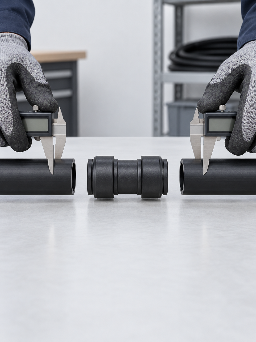
Installers can compare connector search terms without inventing dimensions or ratings.
| Buyer search term | What it may indicate | What must be confirmed | Safe procurement language |
|---|---|---|---|
| Microduct Connector 7mm | Small-diameter connector family or nominal tube reference | Exact OD/ID, tolerance, wall and seal range | “Connector for the approved 7 mm drawing,” not a universal rating |
| Microduct Connector 10mm | Connector intended for a larger nominal duct reference | Actual tube OD, insertion depth and pressure-test method | “10 mm class only after drawing match” |
| 10 Mm Microduct Straight Connector | Straight inline joint between like-size ducts | Whether the part is straight, reducer or gas/water-block type | “Straight connector for equal approved ends” |
| Micro Duct Connector 7/5.5mm | Two-dimension shorthand, possibly OD/ID or a range | Which dimension each number represents and seal geometry | “7/5.5 mm per supplier drawing” |
Tool-free push-fit installation still requires preparation, seating and visual checks.
Many push-fit microduct connectors are designed for hand installation, but the reliable sequence remains disciplined. Cut the duct square, remove debris, keep the end round, and mark the insertion depth if the instructions provide one. Push until the tube reaches the internal stop; then fit the retaining clip or secondary lock when specified. A straight connector joins like-size ends. A reducer is a different selection decision and should never be improvised by forcing one tube into the wrong port.
Make a visual check from both sides: the tube should be fully inserted, the connector body should not be cocked, and no seal should be pinched or visible outside its seat. Take a photo for the installation record. If a duct is under side load, support it before testing so the joint is not used as a bend anchor.
For background on tube behaviour and handling, see the site’s HDPE microduct guide for fiber installers. It complements, but does not replace, the selected connector’s drawing.
Seal inspection and the approved pressure test determine whether a connector can stay in service.
O-rings and sealing lips are consumable interfaces. Inspect for cuts, flattening, hardening, swelling and embedded grit whenever a joint is reopened. Replace the seal or the complete body when the manufacturer’s instructions call for a matched kit, when the housing is cracked, or when a correct re-seat and clean test still fail. Do not mix an apparently similar seal compound without compatibility evidence.
Use the project’s pressure or leak test method after assembly. First stabilise the test setup, then record the applied condition, hold time and acceptance criterion from the approved specification. A pressure drop can also come from an open end, a hose, a temperature shift or another connector; isolate sections before blaming the 7 mm fitting. No generic pressure or temperature rating should be assigned to a Microduct Connector 7mm without a part-specific document.
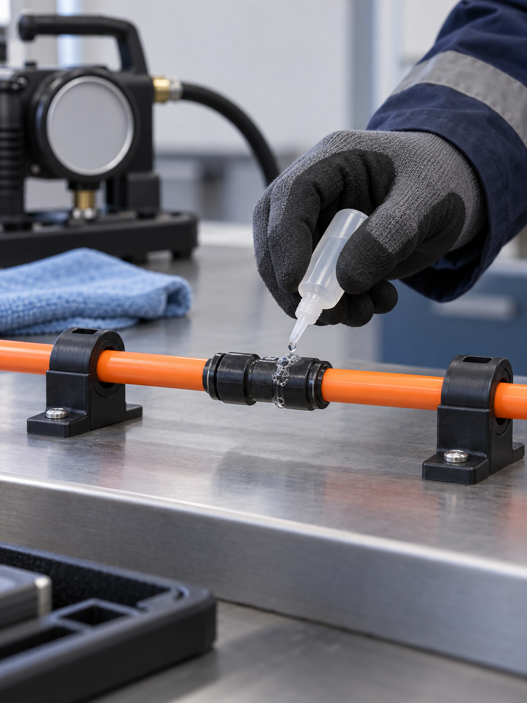
Small microduct connectors fit FTTx routes only when their function and dimensions match the duct system.
Small connectors are commonly considered at cabinet entries, distribution points, access chambers, repair cuts and blown-fiber routes where the duct size and connector family are already defined. Suitability depends on the duct material, route environment, installation method and the connector’s verified range. “FTTx compatible” is a project relationship, not a blanket certification.
For a direct replacement, record the existing connector’s visible geometry, the tube drawing and the reason for replacement. For a new build, define whether the joint must remain accessible, tolerate outdoor exposure, block gas or water, or simply protect an aligned straight run. The function determines whether you need a straight connector, reducer, end stop or a gas/water-block design.
The right choice changes when a project needs a straight joint, a reducer or a closure.
| Choice | Use when | Compatibility evidence | Maintenance/TCO implication |
|---|---|---|---|
| Straight connector | Two approved duct ends are the same size | Equal OD/range, insertion stop and seal kit | Simple inventory; easy visual inspection |
| レジューサーコネクター | Two duct sizes must transition | Port-by-port dimensions and transition drawing | More selection risk; label both ends clearly |
| Gas or water block | The joint must provide a specified barrier function | Part-specific activation and test instructions | Higher process discipline; avoid substituting a cover |
| End stop or cap | A duct end is being terminated or protected | Termination function and approved end size | Useful for staged work; not an inline joint |
Application conditions should determine the evidence and inspection plan for each connector size.
| アプリケーション | Primary decision | Inspection evidence | Typical risk if underspecified |
|---|---|---|---|
| Cabinet repair | Match existing duct and access constraints | Measured OD, photos and connector drawing | Repeat visit or cut-back of a short duct |
| New FTTx branch | Choose family before ordering duct coils | Approved bill of materials and drawings | Mixed inventory and failed first-fit |
| Outdoor chamber | Confirm environmental and closure evidence | Supplier test documents for exact part | Moisture, contamination or unplanned maintenance |
| Temporary staged route | Protect open ends and define handover checks | Temporary-use instruction and end-stop plan | Debris ingress before fiber blowing |
Standards and test documents clarify evidence without creating a generic 7 mm rating.
Ask for the connector manufacturer’s dimensional drawing, installation instruction and test method first. If a project references an enclosure ingress code, IEC 60529 explains the scope and method of IP tests; it does not create a universal pressure rating for a microduct connector. Other ISO or IEC documents may be relevant to a customer’s duct, cable or environmental requirement, but applicability must be checked against the destination market and intended claim.
Where a telecom specification cites IEC 60794-1-2 Method E1, treat it as the named cable test method only. It does not turn “7 mm” into a complete connector specification or certify a connector body, seal or installation; the selected connector drawing and its own evidence remain controlling.
Keep “tested to a method,” “supplied with a test report” and “certified” as separate statements. Procurement should request the sample configuration, dimensions, conditioning and acceptance criteria behind any numerical claim. A supplier’s public installation guidance from Dura-Line, Emtelle, Hexatronic or Solifos can inform practice, but only the selected part document controls the final fit.
Five checks before ordering prevent a search term from becoming a costly specification error.
- Write the exact tube OD, wall thickness, tolerance and material on the purchase request.
- State whether “7 mm,” “10 mm” or “7/5.5 mm” is a nominal label or a drawing dimension.
- Choose straight, reducer, end-stop or gas/water-block function before comparing prices.
- Request seal material, replacement guidance and the approved pressure/leak-test method.
- Plan a sample fit and photo record before releasing a larger installation batch.
Microduct Connector’s Microduct Straight Connector 7 page can be used as a starting point when that URL resolves for your project. If the page or drawing does not match your tube, use the confirmed マイクロダクトストレートコネクタ page and ask for the exact dimensional document rather than guessing from the keyword.
These answers cover the practical questions behind Microduct Connector 7mm searches.
How can the Microduct Connector 7mm join ducts with different wall thicknesses?
It can do so only if the selected product drawing explicitly covers both duct dimensions and provides the correct seal geometry. If not, choose a compatible reducer or another connector family; never rely on insertion force as proof of compatibility.
What temperature range should the Microduct Connector 7mm withstand?
Use the temperature range stated for the exact part, seal and installation environment. A generic “7 mm” search term does not establish a rating, so request the supplier document and consider storage, installation and service temperatures separately.
How can installers visually check that the Microduct Connector 7mm is fully seated?
Confirm that the tube reaches the specified stop or insertion mark, the body is square to the duct, the seal is not exposed or pinched, and every retainer is engaged. Record a clear photo before applying the approved test.
When should the seals or body of the Microduct Connector 7mm be replaced?
Replace seals showing cuts, flattening, hardening, swelling or contamination, and replace a body that is cracked, distorted or still leaks after correct preparation. Follow the manufacturer’s matched-kit instruction where one is provided.
Where can installers use the Microduct Connector 7mm in fiber and telecom networks?
Potential locations include cabinet entries, access chambers, branch routes and repair sections where the duct drawing and environmental requirements match. Confirm the exact connector function before using it in an FTTx route; “FTTx” alone is not a product approval.
How do you choose the correct duct diameter for the Microduct Connector 7mm?
Measure the duct outside diameter, check wall thickness and tolerance, and match those values to the connector drawing and seal range. Clarify whether 7 mm refers to OD, ID or a nominal family label, then verify with a sample fit and test.
Use the references and the selected drawing to confirm the next connector order.
- IEC 60529: Degrees of protection provided by enclosures.
- Dura-Line microduct resources.
- Emtelle microduct installation resources.
- Hexatronic fibre infrastructure resources.
The dependable buying rule is to specify the tube first and the search term second. For a 7 mm, 10 mm or 7/5.5 mm requirement, review the available straight connector option and contact Microduct Connector with your drawing, environment and test requirement before approving the order.


