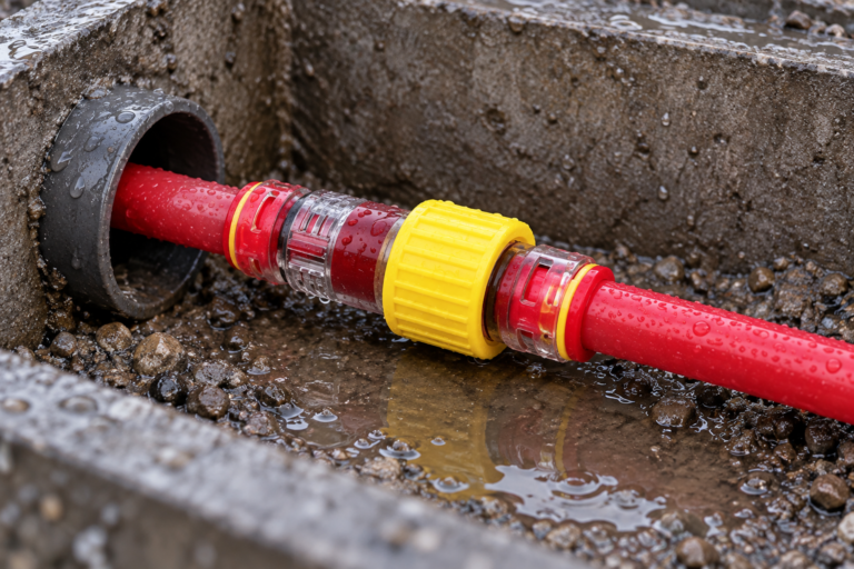
When a construction supervisor in Glasgow found water inside a capped microduct, he asked the crew to add a stronger clip. The clip prevented accidental release, but the next pressure check still showed leakage. Inspection found grit across the end-stop O-ring: retention and sealing were separate functions, so changing the clip could not repair the contaminated seal.
Resumen: A Microduct Locking Clip restrains a connector’s release mechanism; it does not create the primary air or water seal. Use a correctly sized end stop to protect an empty duct, a coupler to join ducts, and a gas-block connector to seal around an installed cable. Pressure-test the complete closure to its approved system limit, inspect the O-ring and tube preparation if it leaks, and use the clip where the connector design or site risk requires release prevention.
Assign retention, closure, joining, and cable sealing to the correct component
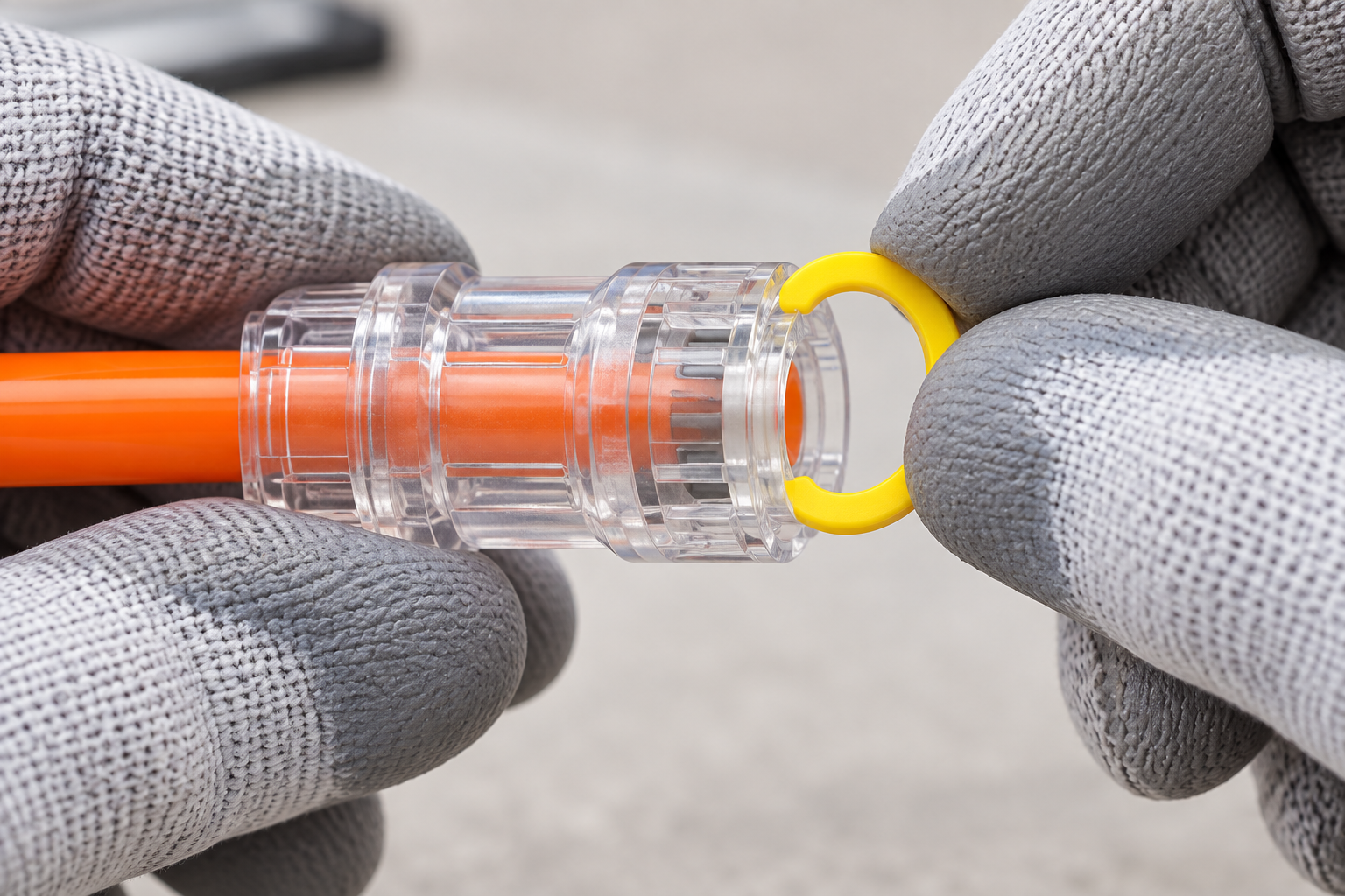
Microduct accessories can look similar but have different jobs. A locking clip blocks movement of a collet or release ring so the duct cannot be disconnected accidentally. An end stop closes an empty duct. A straight connector joins two ducts. A gas block closes the annular space around a cable. Confusing these functions leads to poor test results and unnecessary parts replacement.
The product page says the clip secures connectors and is removed before disconnection. These are retention claims, not pressure-sealing claims. The end-stop and gas-block comparison explains the closure choice.
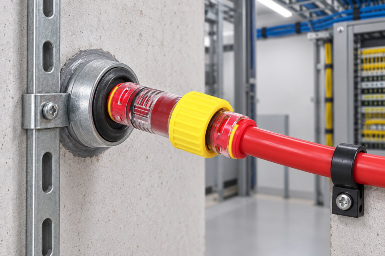
Clips add the most value where a connector may see accidental axial pull or repeated disturbance: crowded handholes, cabinet entries, cable-blowing setups, temporary construction routes, or spans exposed to vibration and maintenance handling. They do not compensate for poor duct support. Restrain and align the route first, then use the compatible clip as anti-release protection when the connector instructions or risk assessment call for it.
| Component | Primary function | Duct state | Pressure-sealing element | Typical decision |
|---|---|---|---|---|
| Locking clip | Prevent accidental release | Empty or occupied | None by itself | Add when design or risk requires retention |
| End stop/cap | Close an open duct end | Empty | Internal seal/O-ring in the closure | Temporary protection or tested closure |
| Acople recto | Join two microducts | Empty or containing cable as designed | Tube-to-body seals | Maintain bore continuity |
| Gas-block connector | Seal around cable and duct | Occupied | Duct seals plus cable-annulus seal | Limit migration at entries or chambers |
Choose an end closure by measured duct OD before adding a retention clip
Before cable installation, an open HDPE microduct needs protection from soil, dust, insects, water splash, and debris that can raise friction or obstruct the bore. Select an end stop by measured duct OD and its declared tolerance. Duct ID or future cable diameter does not determine the cap’s gripping interface. Measure ovality and reject crushed, scored, or heavily weathered ends.
Cut the tube square, remove loose burrs, clean the outside surface, mark insertion depth, and seat the closure fully. Add Microduct Lock Clips only in the configuration intended by the closure maker. A clip from another connector family may appear to fit while failing to restrain the correct moving part. For recurring loose-cap causes and corrections, see the microduct end-cap troubleshooting guide.
Record and inspect temporary closures. Remove the cap only after depressurizing, and never leave it loose before blowing.
Confirm seating visually: the clip should occupy the maker-defined gap between the connector body and collet or locking ring, sit squarely, and show no spreading, partial engagement, or interference with adjacent parts. Replace a clip that is cracked, whitened from stress, heat-distorted, chemically attacked, loose after seating, or no longer returns to its intended shape. Do not stack clips or force the wrong geometry into place.
Pressure-test the sealing assembly and inspect clip retention separately
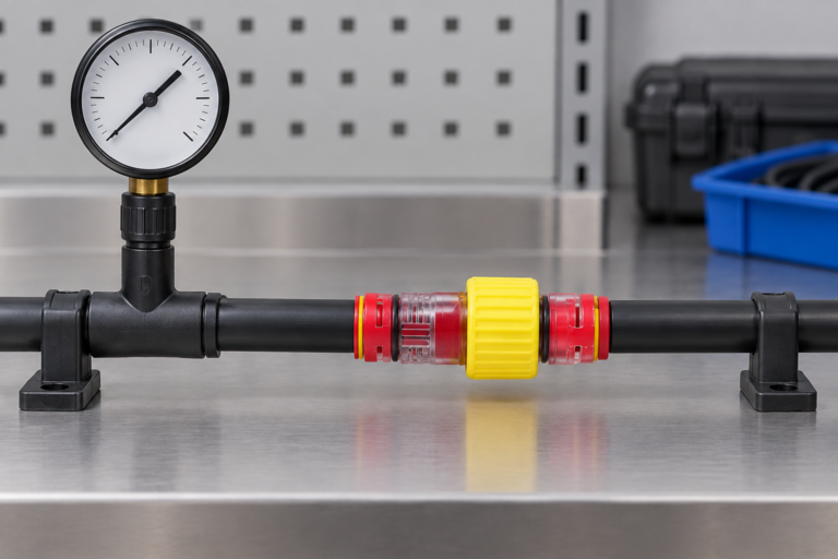
A pressure test can confirm the assembled end stop, tube interface, and route under specified conditions. It cannot prove that Clips for micro duct connector are “sealing,” because the clip is not the seal. If leakage occurs, isolate and depressurize, then check the tube size and cut, insertion depth, O-ring position and condition, closure body, side load, and route connections. Check clip engagement separately as a retention inspection.
Define medium, target, ramp, stabilization, hold time, allowed decay, temperature, instrumentation, restraints, and exclusion zone. Pressurize in stages and never exceed the lowest-rated component.
If a schedule includes 16 bar, treat it as a supplier and product-data verification checkpoint. Confirm the exact end stop or gas-block code, rating type, medium, test duration, temperature, and assembly; never infer that a clip creates or upgrades a 16 bar rating. IEC 60529 IP testing likewise concerns a defined assembly and condition, not an automatic field certification.
| Inspection item | What to check | Failure sign | Acción correctiva |
|---|---|---|---|
| Duct end | Correct OD, roundness, square clean cut | Scoring, ovality, burr, embedded grit | Recut or replace damaged section |
| O-ring/seal | Clean, elastic, correctly seated | Cut, flat spot, swelling, hardening | Replace with specified seal |
| End stop | Full insertion and undamaged body | Visible gap, crack, distortion | Reseat or replace after depressurizing |
| Locking clip | Correct family, fully engaged | Loose, fractured, wrong geometry | Fit correct clip; do not force |
| Pressure result | Stable within approved criterion | Decay, bubbles, audible leakage | Locate root cause and repeat full test |
| Outdoor condition | UV, temperature, impact exposure | Chalking, brittleness, crazing | Replace and review material evidence |
Change to a gas block when the installed cable creates an annular pathway
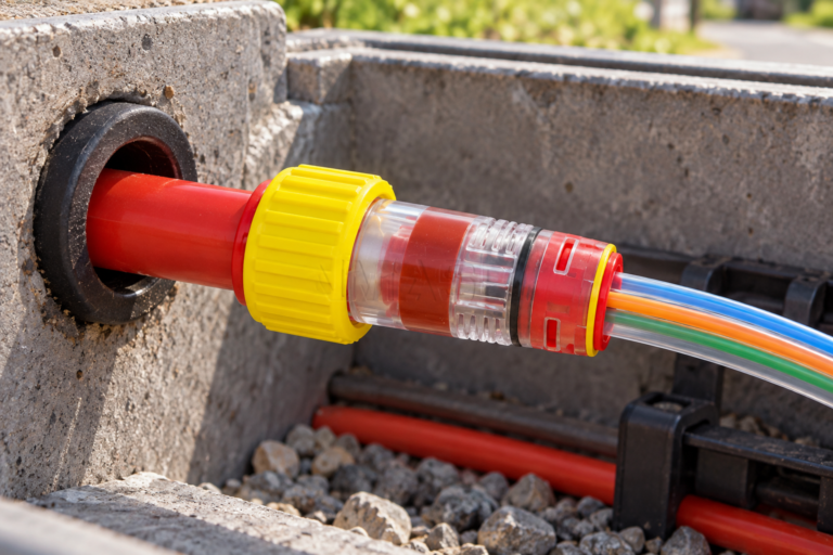
An end stop is removed before cable installation. After cable placement, a gas-block connector may be required where water, humid air, particles, or gases could migrate along the annulus. Choose it using both duct OD and cable-diameter range, keep its annular seal relaxed during blowing unless the instructions say otherwise, then activate and test it.
A compatible clip can prevent gas-block release but cannot replace seal compression. A gas block likewise does not replace a wall penetration, firestop, or hazardous-gas system.
The published waterproof air gas-block range provides one functional contrast with a clip-secured end closure. Compare exact dimensions, instructions, and evidence before changing from temporary protection to permanent occupied-duct sealing.
Verify zero pressure before removing the clip and releasing the collet
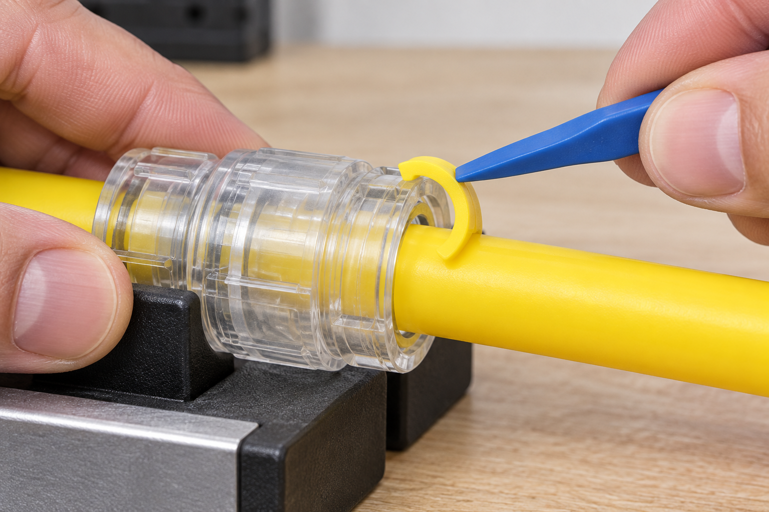
Verify the route, isolate and depressurize it, then clean the fitting. Remove the clip with the specified tool, release the collet evenly, and withdraw the supported tube axially. Twisting against an engaged grip can score HDPE.
Do not rely only on closing a valve or watching a gauge fall. Vent through the approved point, wait for the reading to reach zero, verify that the gauge and vent path are functional, and check that no trapped section remains behind a closed valve or blocked bore. Only then remove the clip. For the common push-fit sequence, take out the clip, press the collet toward the connector body, and keep it depressed while pulling the tube straight out; follow the exact product instruction if its release geometry differs.
Inspect the released tube and trim back to sound material if permitted by the route allowance. Inspect the clip for cracks or loss of shape; inspect the connector’s O-ring and body separately. Reuse only where the manufacturer allows it and all acceptance checks pass. After reassembly, repeat the leakage and retention checks from the beginning.
Verify outdoor material evidence without treating test methods as certifications
For outdoor clips, request polymer identity, temperature limits, UV method, duration, and retained properties. ISO 4892-3 is a fluorescent-UV method, not a product certificate or lifetime guarantee.
- IEC 60529: IP classification and ingress testing for a defined enclosure assembly.
- ISO 4892-3: artificial UV exposure method for plastics using fluorescent lamps.
- ITU-T L.79: optical cable elements for microduct blowing, supporting system-level installation planning.
- ITU-T L.106: optical-cable needs in access networks, relevant to closure environment and route design.
Unsupported pressure, IP, UV, or lifetime claims can lead to rejected submittals and repeat site visits. Tie every claim to the exact part, tested configuration, method, and acceptance criterion.
Select the seal first, then decide where anti-release retention is justified
- State whether the duct is empty, joined, occupied by cable, or crossing a building boundary.
- Select the sealing component first; then decide whether a compatible release-prevention clip is needed.
- Approve exact OD and cable ranges, installation tools, and safe removal instructions.
- Define separate leakage and retention checks with documented acceptance criteria.
- Plan the transition from temporary closure to cable installation so no cap or activated seal obstructs blowing.
Zhejiang Oulu supplies locking clips, connectors, and gas-block fittings as related product families. Buyers should request confirmation of compatibility between exact codes rather than mixing accessories based on appearance.
Questions installers ask before fitting or removing a locking clip
What pressure test confirms that the Microduct Locking Clip is sealing correctly?
No pressure test confirms the clip alone is sealing because the clip is a retention device. Test the complete connector or end-stop assembly to its approved method, then inspect clip engagement separately.
Is a locking clip needed with every Microduct Locking Clip?
The phrase refers to the clip itself, so a second locking clip is not inherently required. Use the quantity and placement specified for the compatible connector and site risk.
How do you remove the Microduct Locking Clip without damaging the duct?
Depressurize, clean the fitting, and use the specified tool to disengage the clip without levering against HDPE. Release the connector collet evenly and withdraw the tube axially.
What UV and temperature rating should an outdoor Microduct Locking Clip have?
It should cover the actual installation and service temperatures and expected sunlight exposure. Verify defined test methods, duration, and retained properties for the exact polymer and clip code.
How can you tell whether the O-ring in the Microduct Locking Clip is worn?
The locking clip itself normally has no sealing O-ring; inspect the O-ring in the associated connector or end stop. Replace it if cut, flattened, swollen, hardened, contaminated, or unable to pass the specified leak test.
Can the Microduct Locking Clip be used for temporary network protection?
It can secure a compatible temporary end stop, but it cannot close an open duct by itself. Use the correctly sized closure, fit the clip as instructed, and include the assembly in inspection and pressure testing.
Use these sources to verify closure, retention, and removal requirements
- IEC 60529, Degrees of protection provided by enclosures (IP Code)
- ISO 4892-3, Plastics—Methods of exposure to laboratory light sources
- ITU-T L.79, Optical fibre cable elements for microduct blowing installation
- ITU-T L.106, Optical fibre cables: Special needs for access network
Choose the seal for the pathway and the clip for retention; asking one part to do both invites the wrong test and the wrong fix.
Review the Microduct fitting Locking Clip and the related conector del bloque de gas, then contact Oulu with the duct state, dimensions, pressure, environment, and required removal controls.