When a controls engineer commissions a small pneumatic actuator, a valve can appear to be the right size and still produce the wrong motion because its three ports were read in the wrong order. The visible fitting may show a supply and working connection, while the exhaust path and the de-energized state remain undocumented. That is why a two-position three-way pneumatic valve should be selected from its schematic, control method and specified port logic rather than from body shape alone. This guide explains the two switching positions, the three-port relationship, normally closed and normally open behavior, and the checks that prevent an unverified assumption from becoming a commissioning fault.
A two-position, three-way valve has two selectable spool or poppet states and three pneumatic ports, commonly supply (1), work (2) and exhaust (3), although numbering must be confirmed on the actual drawing. In one state, supply is connected to the work port; in the other, the work port is connected to exhaust or another defined port. Whether the valve is normally closed or normally open determines the rest state, and an electrical coil is only one possible actuator. Verify the symbol, port numbers, medium, pressure range and reset method in the current manufacturer documentation before installation.
Identify the Two Flow States and Three Ports
“Two-position” describes the number of stable or commanded flow configurations, not the number of physical components. A monostable valve normally has one actuated position and a spring-return position; a bistable valve can retain either position after a pulse, depending on its design. “Three-way” describes three flow connections. In a common pneumatic naming scheme, port 1 is supply, port 2 is the actuator or work port, and port 3 is exhaust, but the drawing supplied with the part controls the interpretation.
In the pressure state, the supply path can feed the work port while the exhaust port is blocked. In the return state, the supply may be blocked and the work port may vent through exhaust. Some circuits use the third port for a second inlet or for a different media arrangement. Those alternatives are possible design patterns, not assumptions about a particular S-VHK2 fitting.
Trace Port Connections on the 3/2 Valve Symbol
A schematic symbol for a 3/2 valve is normally drawn as two adjacent boxes, one box for each position, with arrows or blocking marks showing the connections in that position. Count the boxes to confirm two positions, then trace the lines from the numbered ports. The symbol tells the reader which passages are open, but it does not by itself establish the valve’s pressure rating, seal material, actuation force or electrical specification.
For a typical circuit with port 1 as supply, port 2 as work and port 3 as exhaust, the logic can be described conditionally:
- If the valve is normally closed, the de-energized or rest state commonly blocks supply to the work port; energizing or actuating it can connect 1 to 2, subject to the symbol and return design.
- If the valve is normally open, the rest state commonly allows the defined supply-to-work path; actuation can move the valve to a blocked or exhaust state.
- If the symbol uses a different port assignment, or if port 3 is a second inlet, the flow description changes accordingly.
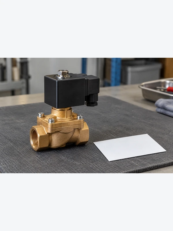
“Energized” therefore cannot be translated into one universal flow result. The coil, pilot, lever or pneumatic actuator must be paired with the specific symbol and reset convention. A product photo is not a substitute for that information.
Define the Valve’s Rest State as Normally Closed or Open
Normally closed (NC) and normally open (NO) describe the valve’s defined rest condition when the actuating signal is absent. In a spring-return solenoid design, that signal may be electrical; in a manually or pneumatically actuated valve, it may be a hand action or pilot pressure. The terms do not describe whether the valve is physically large, fast or suitable for a particular cylinder.
| State or question | Typical NC interpretation | Typical NO interpretation | What must be verified |
|---|---|---|---|
| Rest, no actuation | 1-to-2 path blocked or otherwise closed | 1-to-2 path available, or the documented normal path | Rest symbol, spring location and port numbering |
| Actuated | 1-to-2 path may open | 1-to-2 path may close or change to exhaust | Actuator type, pilot requirement and symbol arrows |
| Work-port release | 2-to-3 may vent if shown | 2-to-3 may vent in the alternate state | Exhaust path, silencer and safe venting arrangement |
The table is a reasoning aid, not a data sheet. A buyer should request a legible circuit symbol and a port map for the exact variant. Documentation from a manufacturer such as SMC or ASCO can help explain product families, but the part-specific drawing remains the controlling evidence.
Write down both the supply and exhaust paths
For a common spring-return, normally closed 3/2 pneumatic valve, the rest state connects the work port A/2 to exhaust R/3 and blocks supply P/1. Actuation connects P/1 to A/2 and blocks R/3. A normally open variant reverses the defined supply-to-work relationship. Tameson’s 3/2-way pneumatic valve guide shows these arrangements. Always reconcile the explanation with the selected model’s symbol, because alternative circuit functions and port assignments exist.
Writing only supply blocked is incomplete if the connected actuator also needs to release air. Trace the work-to-exhaust path and identify any silencer, tubing or shared exhaust connection. A restriction in that path can change actuator behavior even when the supply connection is correct. Exhaust backpressure and the valve’s permitted operating conditions must be reviewed against the actual application, rather than inferred from the nominal port size.
A bistable valve needs a separate state description because it can retain the last selected position after the command is removed. Do not assign it a spring-return NC or NO behavior without documentation. When the load is an actuator, the pneumatic cylinder guide provides context for the driven component; it does not establish what that actuator will do on loss of power or air in a particular machine.
Confirm the valve function from its model drawing
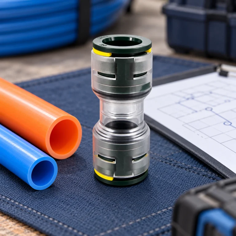
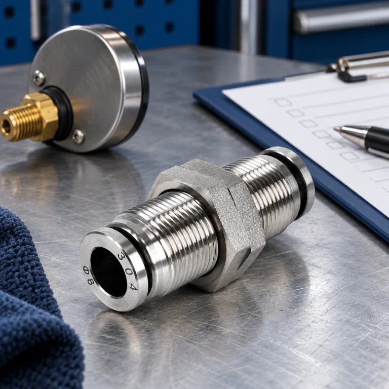
The supplied S-VHK2 images show an external pneumatic valve fitting and its quick-change connection geometry. They are useful for identifying the visible interface and for discussing how a fitting is presented in a product record. They do not show an energized coil, a spring position, an internal spool, a hidden exhaust passage or a complete circuit symbol. It would therefore be inaccurate to label the photograph as proof of a solenoid valve or to claim that it depicts a 3/2 internal layout.
Compare Manual, Pneumatic, and Electrical Actuation
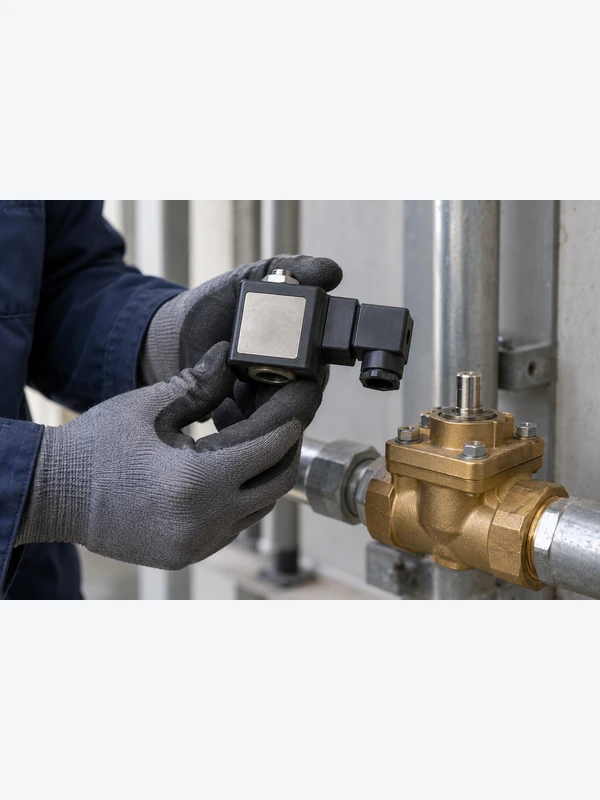
A three-way valve can be actuated manually, mechanically, pneumatically or electrically. The flow principle is still based on selecting one of two internal connection states, but the commissioning risks differ. A manual lever needs access and a clear operator indication. A pneumatic pilot needs a defined pilot signal and return condition. A solenoid arrangement needs voltage, coil duty, suppression and a control circuit that matches the valve documentation.
| Actuation | Useful when | Evidencia a solicitar | Common mistake |
|---|---|---|---|
| Manual | The operator can reach and observe the valve | Handle positions, lockout method and port symbol | Assuming the handle position proves internal flow |
| Pneumatic pilot | A remote air signal is already available | Pilot pressure window, pilot medium and reset behavior | Ignoring pilot pressure loss or exhaust routing |
| Electrical solenoid | Control logic needs remote switching | Coil voltage, duty, connector, manual override and wiring diagram | Calling any photographed fitting a solenoid valve |
Check pilot pressure during startup and pressure loss
Internal pilot operation uses the valve’s supply conditions to generate the switching force. A circuit may have adequate pressure during normal running but not during initial pressurization, a downstream equalization condition or a controlled shutdown. Check the documented pilot requirements in each operating state. A maximum pressure rating says nothing about whether a conventional pilot mechanism can switch at zero differential.
External pilot arrangements use a separately specified control-air connection. They can address some circuit conditions that an internal pilot cannot, but only when the chosen model supports the arrangement and the pilot supply remains within its limits. Direct-acting designs operate differently again. Do not adopt a minimum pressure quoted for a different valve family or assume that every three-port valve supports vacuum or reverse flow.
Review the broader Gamma de componentes neumáticos alongside the circuit drawing to identify the required interfaces. Keep supply preparation, control air, tubing and valve functions distinct in the bill of materials. If commissioning results differ from the symbol, record supply, pilot signal, commanded state and work-port response before changing the configuration.
For fault finding, isolate and release stored energy under the machine procedure before opening tubing or serviceable parts. Verify that the mechanical load is supported where necessary. Reconnecting ports by trial and error can conceal the original discrepancy and create an unintended motion; resolve the model and circuit mismatch first.
Check Port, Tube, Exhaust, and Isolation Conditions Before Testing
Start with isolation and depressurization under the machine’s approved procedure. Confirm Diámetro exterior del tubo, port thread and seal method independently; a fitting that starts in a port can still have the wrong thread. Route the exhaust so it cannot introduce dirt or create a hazard, and support tubing so bending loads are not transferred to the connector.
Before connecting control power or pilot air, trace the intended sequence on the schematic: which port supplies the actuator, which state should hold it, and where the air should release when the signal is removed? Test each state at controlled pressure and record the observed port behavior. If the result differs from the drawing, stop and resolve the documentation or wiring discrepancy rather than swapping ports by trial and error. For related interface guidance, see the site’s article on pneumatic coupling applications.
Verify both states before commissioning
- Obtain the exact part number, symbol, port map and actuator description.
- Define the normal state required when the signal is absent: closed, open, vented or another documented condition.
- Check medium, pressure, temperature, flow demand, tube size and thread standard against current data.
- Confirm control details such as coil voltage or pilot pressure, reset method, connector and manual override.
- Plan a functional test for both positions and document the observed supply, work and exhaust paths.
For background on electromagnetic actuation, compare this checklist with the site’s explanation of what a solenoid valve does and its overview of solenoid valve classifications. Those articles provide general context; they do not replace the drawing for a specific valve.
Preguntas frecuentes
What is a two-position, three-way pneumatic valve?
It is a directional valve with two selectable flow states and three pneumatic ports. The ports may be assigned as supply, work and exhaust, but the exact assignment must come from the valve symbol or drawing.
How does a 3/2 pneumatic valve work?
One position connects a defined pair of ports and blocks or routes the remaining port; the second position changes that relationship. In a common 1–2–3 arrangement, the work port may switch between supply and exhaust, but alternate port assignments exist.
What is the difference between normally closed and normally open?
Normally closed and normally open describe the documented rest state with no actuation signal. NC commonly blocks the supply-to-work path at rest, while NO commonly leaves that path available; the symbol and manufacturer documentation decide the actual flow.
Does a two-position, three-way valve have to be a solenoid valve?
No. The same two-position, three-port logic can be actuated manually, pneumatically, mechanically or electrically. A solenoid is only one actuation method, so an external fitting photograph cannot prove that a coil is present.
What do ports 1, 2 and 3 mean on a pneumatic valve?
Many schematics use 1 for supply, 2 for work and 3 for exhaust, but numbering conventions and circuit functions can vary. Confirm the legend, body markings and current part drawing before connecting tubing.
What should be checked when the valve switches but the actuator does not move?
Check supply pressure, port assignment, exhaust restriction, tube seating, pilot or coil signal, and the actuator’s mechanical load. Compare the observed connections in each state with the symbol; do not infer an internal blockage from the external appearance alone.
Do all 3/2 solenoid valves need inlet pressure to switch?
No. Direct-acting, internally piloted and externally piloted designs have different requirements. Check the exact model’s supply and pilot-pressure limits, including startup and depressurized conditions. Do not apply one universal minimum differential to every 3/2 valve.
Can a bistable 3/2 valve be treated as normally closed on power loss?
Not without model-specific evidence. A bistable design may retain its last state instead of returning to a spring-defined position. Document both commanded states and the response to loss of electrical power or pilot air as part of the circuit review.
Referencias
- SMC directional-control valve catalog (official product categories; use the exact model documentation for ratings and circuit data).
- SMC pilot-operated three-port solenoid valve catalog (a documented electrical-actuation category, not identification of the pictured fitting).
- Emerson ASCO official valve resources (manufacturer reference for valve families and application documentation).
- Tameson: 3/2-Way Pneumatic Valve—Operation and Port Configurations
Resumen
A two-position, three-way valve is defined by its two flow states and three ports. Confirm the model’s supply, work and exhaust assignments, then identify the rest or retained state and the actuation method. Check pilot conditions during startup and pressure loss as well as normal running. Commission both states against the drawing and record the results; neither an external fitting photograph nor an audible switch confirms the complete pneumatic function.