
A 14 mm duct connection can appear correct while the cable seal remains unsuitable. The duct dimension identifies only one interface; a cable passing through the fitting introduces a second interface with its own diameter range and assembly condition. Procurement teams therefore need more than a matching size label before approving a building-entry connection. Confusing the two can lead to unsuitable stock, repeated assembly work, or a commissioning result that does not represent the finished installation. The useful questions are what the exact connector code accepts, which state its pressure statement describes, and what must be checked when the cable is changed. These distinctions determine whether the selected part fits the complete pathway.
The short answer is that a 14mm Gas Block Microduct Connector must match both the duct and the occupied cable annulus. The published FZA14/12 7-10 model page states 10 bar blowing pressure, an open state for cable blowing, ring rotation to seal afterward, and two separately ordered locking clips. Its 7-10 selection range is not compatibility with every cable used in a 14 mm duct. Confirm dimensions and the supplied seal, then obtain a separate cable-sealing acceptance procedure. The blowing statement alone does not establish the pressure at which the occupied seal should be tested.
What do 14/12 and 7-10 mean when selecting the connector?
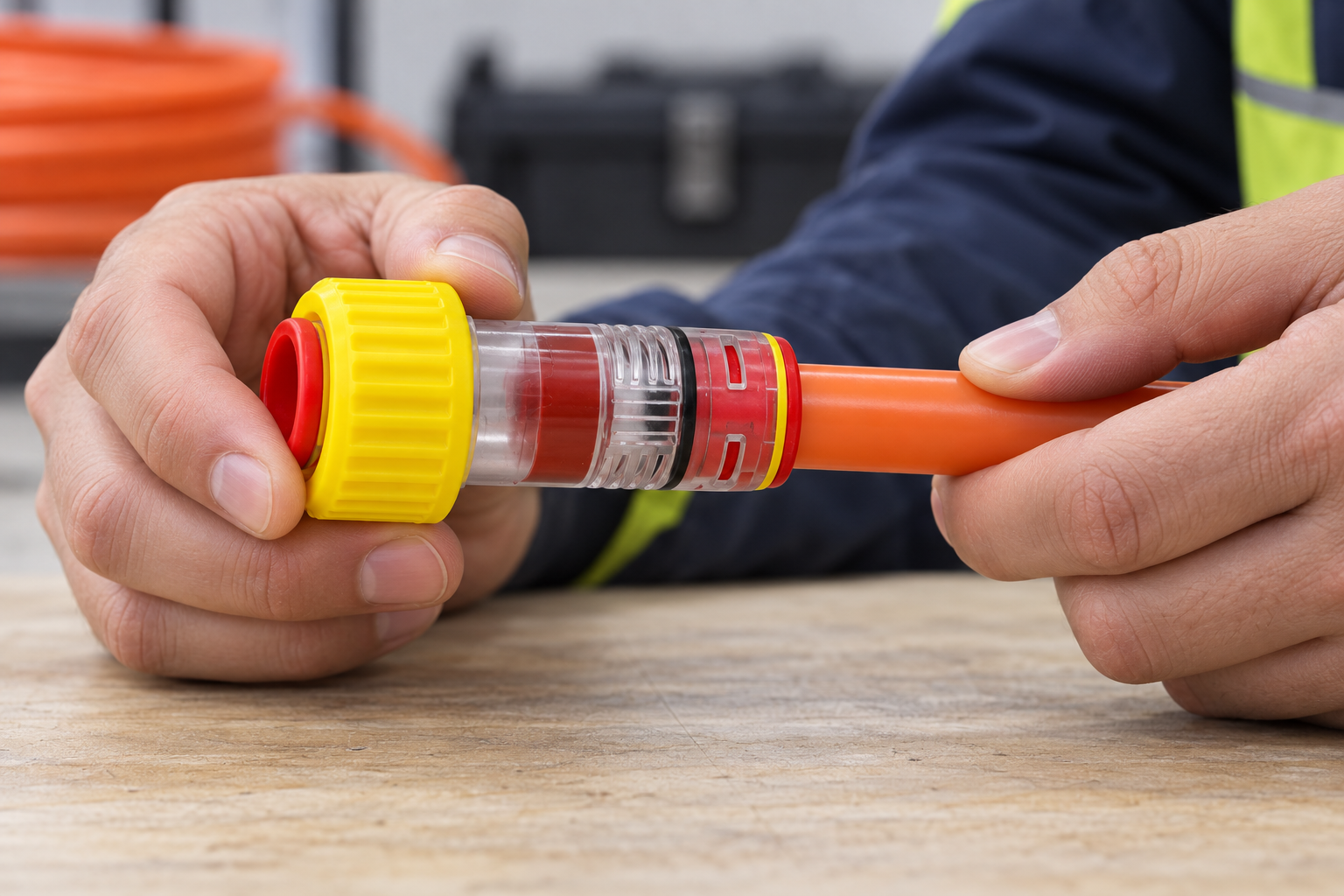
Microduct schedules commonly express outside and inside diameter together. Accordingly, 14/12 is an OD/ID interpretation of 14 mm outside diameter and 12 mm inside diameter, subject to confirmation against the manufacturer’s dimensioned drawing. It is not a measurement of the delivered tube. The published 7-10 selection range concerns cable outside diameter; verify its units, limits and applicability to the seal actually supplied.
Measure the duct away from a damaged end and check roundness as well as diameter. Compare the cable manufacturer’s diameter tolerance, not just its nominal value, with the confirmed cable sealing range. A cable specified near either boundary deserves sample approval using the production jacket and duct. Ovality, surface condition and local jacket damage can affect the assembled contact even when the nominal numbers match.
Do not confuse duct size with cable diameter; the microduct connector size and pressure comparison explains broader selection. Record the approved cable type alongside the connector code so substitutions trigger review.
How does a gas block differ from an end stop or locking clip?
The selection depends on whether the duct is vacant or occupied. An empty-microduct end cap closes a vacant pathway; it cannot form a compatible seal around an installed cable. A clip acts on the release mechanism rather than replacing either sealing interface. The end-stop and gas-block comparison explains when the closure duty changes.
| Component or condition | Svrha | What it does not establish | Selection check |
|---|---|---|---|
| Occupied-duct gas block | Seal the cable annulus and connect the specified duct | Compatibility with every cable fitting inside the duct | Duct drawing and cable-seal range |
| Empty-duct end stop | Close an unused duct end | A seal around an installed cable | Duct size and approved closure conditions |
| Locking clip | Prevent inadvertent release where specified | Correction of wrong dimensions, cracks or incomplete seating | Correct clip and fitting position |
| External protective cover | Protect the fitting as its instructions define | An independent gas seal or direct-burial qualification | Declared environment and complete assembly |
When should the FZA14/12 cable seal be activated?
For this published model, the sequence is open for blowing, then rotate the ring to seal after cable placement. Follow its installation instructions for insertion depth, ring travel and any assembly limits; do not invent a tightening torque. This sequence is not universal: passive seals and other designs can have different preparation and operating states.
Prepare clean, round, undamaged duct ends and avoid burrs or angled cuts. FCST’s 2025 connector installation instructions provide a useful external manufacturer example: a tube may be gripped without being fully seated, which can cause leakage. Apply the exact maker’s procedure rather than importing another manufacturer’s tolerances or insertion depth.
Record duct seating, cable inspection, seal setting and test completion. Confirm whether the FZA model’s two separately ordered clips are included. Clips cannot correct jacket damage or side loading. At building or ODF transitions, support the duct and address wall-penetration sealing separately.
How should the two interfaces be tested and diagnosed?
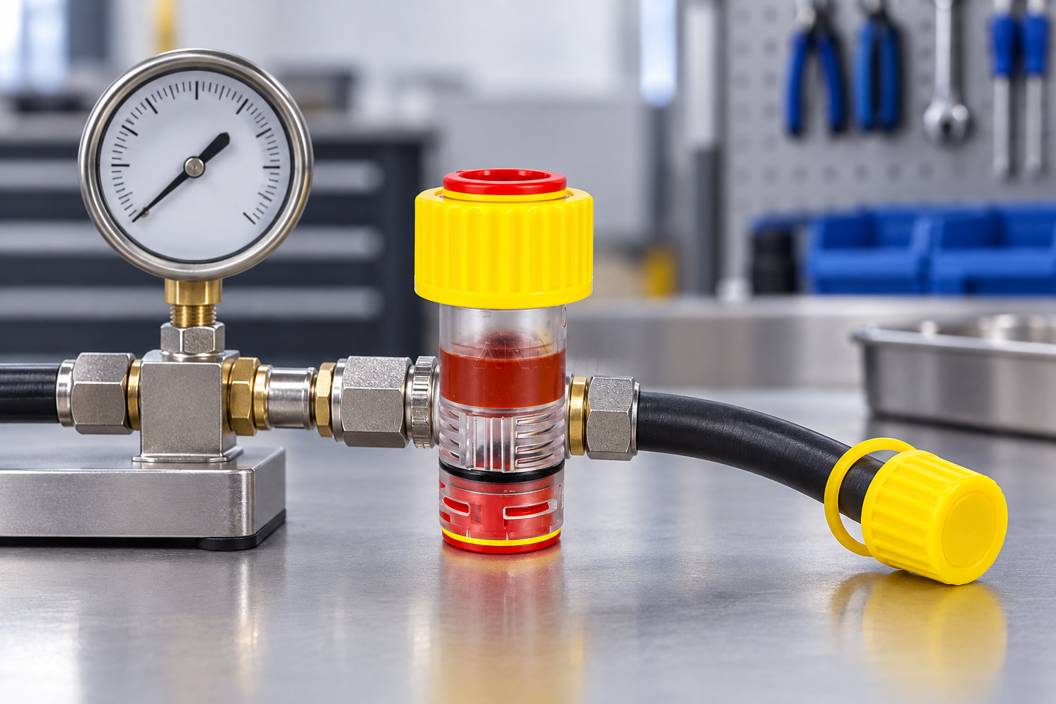
Separate blowing-state capability from occupied-cable sealing. The model’s 10 bar statement is not a published cable-seal test pressure. Request a model-specific procedure identifying medium, assembly state, pressure or exposure, duration and acceptance criterion. An empty-duct pressure test does not verify the annulus around the installed cable.
| Observation | Possible issue to investigate | Next action |
|---|---|---|
| Leakage at the duct connection | Incomplete insertion, damaged surface or wrong duct fit | Depressurize; inspect dimensions, preparation and seating |
| Leakage around the cable | Wrong seal range, jacket defect or incorrect seal state | Confirm the supplied seal and production cable; reassemble as instructed |
| Pressure change without a located leak | Temperature change or another route interface | Use the approved stabilization procedure and isolate sections |
| Water near the fitting | Local ingress or water arriving from elsewhere in the pathway | Trace the route and test suspected interfaces separately |
Use a controlled, approved method with suitable instruments and depressurize before release. Record connector code and lot, duct and cable geometry, assembly state, medium, instrument, test conditions and result. After cable replacement or seal disturbance, the previous result no longer validates the changed assembly: inspect and retest before acceptance.
What evidence should procurement request for a building-entry connection?
EN 50411-2-8:2009’s official catalogue scope covers initial dimensional, optical, mechanical and environmental requirements for installed blown-fibre microduct connectors in protected installations. It excludes connectors intended for direct sunlight. A catalogue reference is not certification of this connector or proof of unrestricted outdoor service.
IEC 60794-5:2014 addresses microduct optical-fibre cables, fibre units and microducts intended for blowing; it does not replace connector-specific qualification. For exposed plastics, ISO 4892-1:2024 provides laboratory light-exposure guidance, not a fixed conversion from test hours to outdoor years. Obtain evidence for the intended enclosure or exposure, and treat firestopping and hazardous-gas protection as separate approvals.
A practical two-interface procurement checklist prevents a size-only approval:
- For the duct interface, request the exact code, drawing revision, accepted OD/ID, dimensional tolerances and preparation requirements.
- For the cable interface, confirm jacket diameter tolerance, supplied seal identity, sealing range and handling limits at its boundaries.
- For assembly and testing, obtain the open/sealed sequence, clip requirements and distinct blowing and cable-sealing evidence.
- For maintenance, establish release instructions, permitted replacement parts, any reuse approval and the retest needed after disturbance.
These are practical procurement controls, not universal statutory requirements.
What else should installers confirm before accepting a 14 mm gas block?
What contaminants does a 14mm Gas Block Microduct Connector block?
Its intended duty is to restrict migration at the specified interfaces. Claims for a particular gas, chemical or water exposure require exact-model evidence; the product name alone does not establish them.
Should the gas or water seal be activated before fiber installation?
The cited FZA model opens for blowing and is sealed by ring rotation afterward. Do not apply that sequence automatically to passive seals or another design.
How is a 14mm Gas Block Microduct Connector installed at a building entry?
Confirm both interfaces, prepare and seat the duct, place the compatible cable, set the seal and test as instructed. Support the pathway and complete the separately approved wall-penetration detail.
What pressure rating suits an outside-plant installation?
Match documented component limits to the route’s defined conditions. The cited model publishes 10 bar blowing pressure, not an occupied cable-seal rating; obtain the missing sealing evidence separately.
How can the connection be tested for air, gas and water leakage?
Obtain medium-specific conditions and acceptance criteria for the exact assembly. An air test is not automatically evidence for water migration or a particular gas exposure.
Can the connector be reopened for cable maintenance?
Only according to its release and reuse instructions. Depressurize, inspect components, replace damaged or non-reusable parts and retest; no universal reuse-cycle allowance applies.
What if the cable is close to the sealing-range boundary?
Check the full jacket tolerance and approve samples with the actual supplied seal. Do not assume a nominal diameter at the limit proves acceptable production variation.
Does replacing a cable preserve the previous leak-test approval?
No. A different jacket diameter or disturbed seal changes the tested interface. Review compatibility and perform the required acceptance test on the new assembly.
How can buyers turn a 14 mm size match into an accepted connection?
A dependable selection begins by separating duct fit from cable sealing, not by treating 14 mm as a complete specification. Confirm the dimensioned drawing, compare the production cable’s tolerance with the supplied seal range, and resolve boundary cases before approving stock. Next, distinguish the published blowing condition from the occupied seal’s acceptance method; do not use the 10 bar blowing statement to fill a missing cable-seal rating. Installation records should identify the assembly that actually passed, and replacement work must trigger inspection and retesting rather than inherit an old result. Send the exact duct, cable and entry conditions when requesting drawings and model-specific evidence from Oulu / ANMASPC.


