
When a machine stops at the end of a stroke, the visible symptom is often a stationary rod, but the cause may be upstream: a control valve may not be switching, a fitting may be leaking, or the cylinder may be underspecified for the load. Understanding how a pneumatic cylinder works helps maintenance and design teams separate air supply, control, mechanics, and installation checks before replacing a component. This article explains the operating sequence and the checks that should be completed before a pneumatic actuator is selected or troubleshot.
Кыскача мазмун: A pneumatic cylinder converts the pressure of compressed air acting on a piston into linear motion. Pressure establishes the available force through the effective piston area, while flow and exhaust control influence speed; the actual result is reduced by friction, seal behavior, load, and installation conditions. Single-acting cylinders use air for one direction and a spring or external load for the return; double-acting cylinders use controlled air on both sides for powered extension and retraction. Before ordering, verify bore, stroke, working pressure, load, speed, mounting, valve flow, tubing, and fittings against the manufacturer documentation. ISO 1219-1 helps teams read the fluid-power circuit; it is not a product rating or certification.
What is a pneumatic cylinder and what does it do?
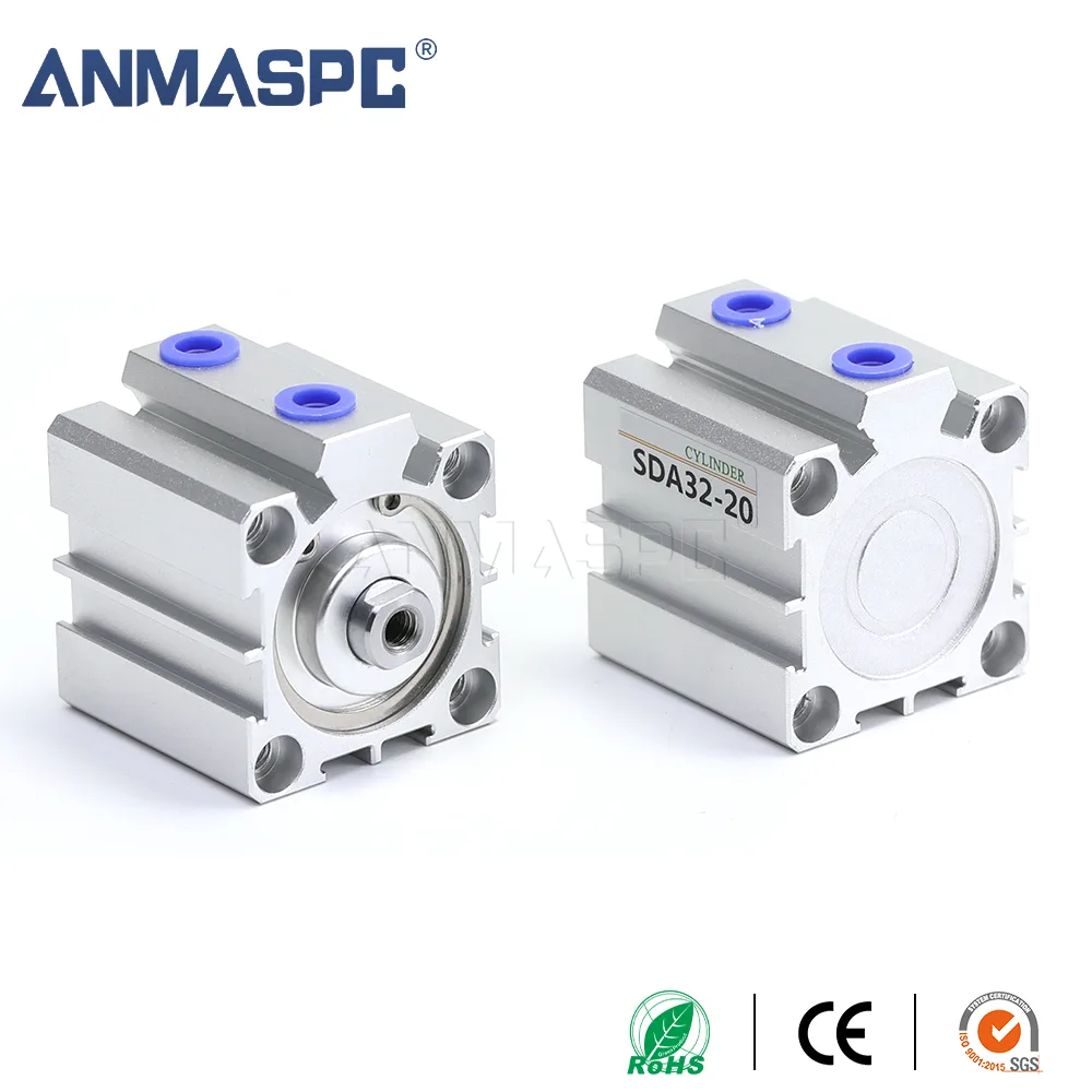
A pneumatic cylinder is an actuator in which compressed air moves a piston inside a cylinder barrel. The piston is connected to a rod, carriage, or other output element, so the air-driven piston movement becomes a controlled linear action such as pushing, clamping, lifting, indexing, or opening a mechanism. The cylinder does not create compressed air; an air source and preparation equipment supply it, and a control valve directs it.
A working circuit normally includes an air source, filtration and regulation, a directional control valve, tubing and fittings, and the cylinder. The what is a cylinder guide gives basic terminology, while this article focuses on the sequence by which air becomes motion and on the evidence required for selection.
How does compressed air create linear motion?
When the valve connects a pressurized supply to one side of the piston, air pressure acts over the piston area. The ideal relationship is often expressed as force = pressure x effective area. In practice, the usable output must account for seal friction, rod and guide friction, pressure losses, acceleration, external load, and the duty cycle. On the rod side of a double-acting cylinder, the rod occupies part of the area, so the effective area is different from the cap side; the manufacturer’s calculation method should be used rather than assuming equal output in both directions.
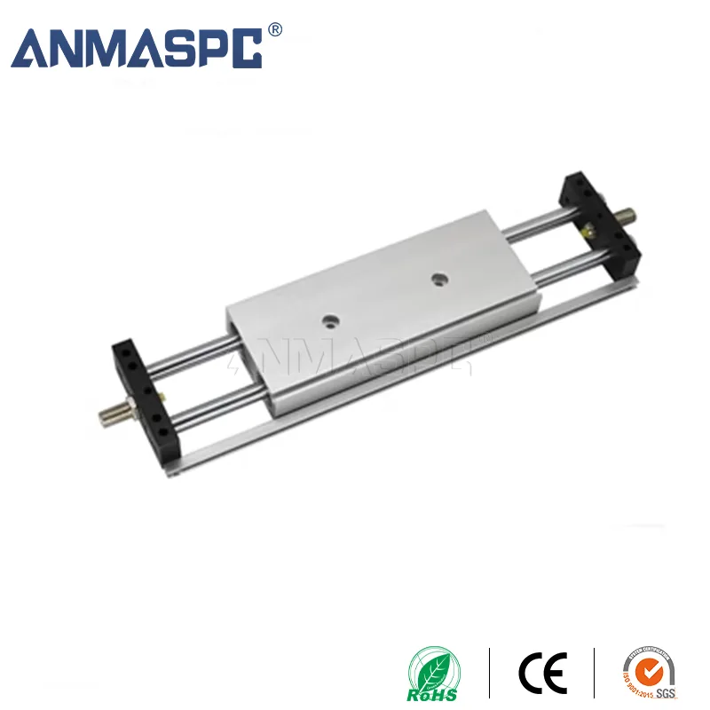
The piston transfers this net force to the rod or carriage. The rod then moves the connected mechanism only if the load path is aligned and the mounting can absorb the resulting forces. Side loading, unsupported masses, impact at the end of stroke, or a binding guide can make a correctly pressurized cylinder appear weak. A cylinder should not be treated as a substitute for a separate guide when the application imposes bending or off-axis loads.
How do the air source and control valve affect cylinder movement?
Air preparation removes contaminants and manages the supply condition before air reaches the valve and actuator. The directional valve determines which cylinder port receives supply and which port exhausts. For a double-acting circuit, changing the valve state reverses the pressure difference across the piston. The solenoid valve control guide explains the control element separately; its coil, porting, response, and electrical interface still have to match the machine design.
Pressure and flow are related but not interchangeable selection variables. Pressure affects the force that can be developed, subject to the cylinder’s documented operating envelope. Flow capacity, tubing length, fittings, valve ports, and flow controls influence how quickly the chamber fills and exhausts. A regulator set to a higher value cannot correct a blocked exhaust, undersized connection, misaligned load, or leak. Commissioning should therefore observe supply pressure at the circuit, valve switching, exhaust behavior, and actual motion under the intended load.
What is the difference between single-acting and double-acting cylinders?
How does a single-acting cylinder return?
A single-acting cylinder uses compressed air for one powered stroke. A spring or an external load returns the piston when the supply is removed or the chamber is exhausted, depending on the design. The return force and available travel are conditional on the selected cylinder and the external mechanism; do not assume that a spring can return an arbitrary load or overcome friction. Verify the spring direction, return time, mounting orientation, and fail position from the product documentation.
How does a double-acting cylinder reverse direction?
A double-acting cylinder has two working chambers. The valve supplies one side while exhausting the other for extension, then swaps those connections for retraction. Because both directions are powered, this arrangement is useful when the load, speed, or return position cannot be delegated to a spring or gravity. Retraction and extension still have different effective areas on a rod cylinder, and the load may differ by direction.
| Салыштыруу чекити | Single-acting cylinder | Double-acting cylinder | Кандай текшерүү керек |
|---|---|---|---|
| Powered movement | Air powers one direction | Air powers both directions | Required motion and fail position |
| Return method | Spring or external load | Controlled air on the opposite chamber | Spring force or reverse-load requirement |
| Force behavior | One powered force direction plus return condition | Different effective areas may apply on extension and retraction | Bore, rod area, pressure, friction, and load |
| Control arrangement | Valve porting must support supply and exhaust sequence | Valve must switch both working ports | Valve function, flow, exhaust, and response |
| Selection risk | Spring travel or return load can be overlooked | Side load, speed, and cushioning can be overlooked | Stroke, speed, mounting, guidance, and duty cycle |
The table describes operating principles, not a universal performance comparison. The cylinder maker’s drawing and data sheet control the permissible pressure, stroke, speed, temperature, load, and installation details for a specific model.
How do cushioning, seals, and fittings influence the result?
End-of-stroke cushioning reduces the impact as the piston approaches a cap. Its adjustment must suit the moving mass and speed; closing a needle or flow control without observing the motion can create a slow or unstable cycle. Seal selection and lubrication requirements likewise depend on the cylinder series, medium, temperature, and maintenance plan. A visible air leak, oil contamination, or stick-slip movement should be investigated rather than hidden by increasing pressure.
Tubing and fittings complete the air path. The connection must match the cylinder port thread, tube outside diameter, sealing method, and environmental conditions. The pneumatic fitting applications guide explains how straight connectors, elbows, tees, and bulkhead fittings affect routing and service access. Cut tubing square, insert it to the documented depth, support moving lines, and leak-check the assembled circuit before putting it into production.
How should a pneumatic cylinder be selected for an application?
Start with the motion and the load, then confirm the complete air circuit. Bore, stroke, pressure, load, speed, and mounting are minimum selection inputs; they are not interchangeable. Record whether the load is guided, whether there is a side force, how the cylinder is mounted, how often it cycles, and what happens if air is lost. Ask the supplier to confirm the calculation with the actual effective area, friction assumptions, cushioning, and duty conditions.
| Application need | Configuration to consider | Evidence to collect before approval |
|---|---|---|
| Push or clamp in one powered direction | Single-acting or double-acting, depending on the return and fail requirement | Return load, spring direction, stroke, load path, pressure, and mounting |
| Powered extension and retraction | Double-acting cylinder with a suitable directional valve | Both direction loads, bore and rod area, speed, valve flow, and exhaust control |
| Short travel in restricted space | Compact body or alternative guided arrangement, if the drawing supports it | Available envelope, port orientation, stroke, connection clearance, and guide support |
| Repeated indexing or positioning | Cylinder with suitable cushioning and external guidance as required | Cycle frequency, moving mass, stop impact, speed control, and alignment |
| Contaminated, wet, or unusual environment | Only a documented seal, body, and protection combination | Medium, temperature, corrosion exposure, cleaning method, and manufacturer limits |
- Define the motion. State the required direction, stroke, speed profile, cycle frequency, and end position; distinguish the guided load from the cylinder rod load.
- Calculate with documented inputs. Use bore, effective area, pressure at the actuator, friction, acceleration, and a stated engineering margin. Do not reuse a force value from a different pressure, rod size, or cylinder family.
- Confirm mechanical installation. Check mounting, alignment, rod support, side-load control, clearances, cushioning, and access for replacement.
- Match the air path. Verify valve function, port thread, tube OD, fittings, flow-control orientation, filtration, regulation, and exhaust routing.
- Test the assembled circuit. Check for leaks, observe extension and retraction under the real load, and record the approved settings and part revisions.
Microduct Connector can help buyers identify compatible pneumatic tubing and fittings, but a product category is not a substitute for a model-specific engineering check. Review the pneumatic fittings range alongside the cylinder maker’s connection drawing and the machine builder’s requirements.
Which standards and documents should be used?
ISO 1219-1 defines fluid-power graphical symbols and circuit diagrams, making it useful for interpreting valve and actuator schematics. It does not certify a cylinder or establish the operating limits of a particular product. For selection, the controlling evidence is the current manufacturer data sheet, dimensional drawing, installation instructions, material and seal compatibility information, and any machinery, pressure, food-contact, or workplace rule that applies in the destination market and intended use.
Keep the selected part number, revision, calculation inputs, test observations, and maintenance instructions with the equipment record. This prevents a visually similar replacement from being treated as automatically equivalent. Where a supplier or marketing page makes a certification or performance claim, request the underlying scope and document before relying on it.
Frequently asked questions about pneumatic cylinders
How does a pneumatic cylinder create force?
Compressed air pressure acts over the piston area, producing a net force that moves the piston and rod. The practical output depends on effective area, pressure at the actuator, friction, rod area, load, and alignment. Verify the calculation with the manufacturer’s data for the selected bore and rod.
What is the difference between a pneumatic cylinder and a compressor?
A compressor generates compressed air; a pneumatic cylinder uses that air to produce linear motion. They are separate parts of the system and must be matched through air preparation, valve control, tubing, fittings, and documented operating conditions.
Is a single-acting or double-acting cylinder better?
Neither is universally better. Choose single-acting when one powered direction and a defined spring or external return meet the task; choose double-acting when both directions need controlled air. Compare the fail position, load, speed, stroke, valve arrangement, and available installation space.
Why is a pneumatic cylinder moving slowly?
Possible causes include restricted flow, a blocked or undersized fitting, low pressure at the actuator, incorrect flow-control orientation, a leak, excessive load, misalignment, or unsuitable cushioning. Isolate the cause by checking pressure, valve switching, tubing and exhaust, then observe the cylinder without changing multiple settings at once.
Can a pneumatic cylinder lift any load if pressure is increased?
No. Increasing pressure cannot correct a load path with side force, a binding guide, inadequate mounting, insufficient effective area, or a component outside its documented envelope. Confirm bore, stroke, pressure, load, speed, mounting, guidance, and safety requirements before changing the regulator setting.
What should be checked before replacing a pneumatic cylinder?
Record the existing bore, stroke, port thread, mounting dimensions, rod or carriage arrangement, single- or double-acting function, pressure, speed, load, environment, and connection details. Compare those records with the replacement drawing and run a controlled leak and motion test before returning the machine to service.
Деректер
- ISO 1219-1: Fluid power systems and components – Graphical symbols and circuit diagrams.
- Festo pneumatic drive documentation, including actuator selection and application information.
- SMC air-cylinder catalog and selection documentation.
The dependable motion is the result of a matched system, not a cylinder in isolation: specify the load path, verify the air path, and test the complete assembly. When you are ready to confirm tubing and fitting choices for a pneumatic cylinder, contact Microduct Connector with the application conditions and the relevant equipment drawing.


