When a fiber-installation supervisor in Rotterdam joined two 12/10 mm ducts before an afternoon blowing run, the compressor gauge fell within minutes and the cable stalled short of the cabinet. The first reaction was to blame the connector; inspection showed a different cause—one duct had an uneven, un-deburred cut and neither end had reached the insertion stop. Re-cutting, cleaning, and using a correctly sized straight fitting restored the line. In air-blown fiber work, selection and installation discipline usually matter more than the label “coupler.”
Кыскача мазмун: A микродукт түз туташтыргыч is normally the right choice for a permanent, in-line joint between two compatible HDPE microducts; it should preserve a smooth bore and a pressure-tight seal for fiber blowing. “Coupler” is a broader term that can include straight connectors as well as reducing, transition, or service fittings. Start with the duct’s сырткы диаметри (OD), not its nominal inner diameter, and prove the assembled section with the project’s specified pressure/hold test before blowing fiber. The IEC 60794-5-20 family addresses outdoor microduct systems for air-blown optical cables, making a documented system-level check more useful than an unsupported pressure claim.
What is the practical difference between a straight connector and a coupler?
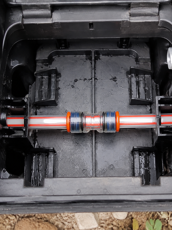
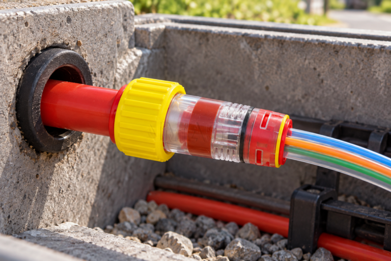
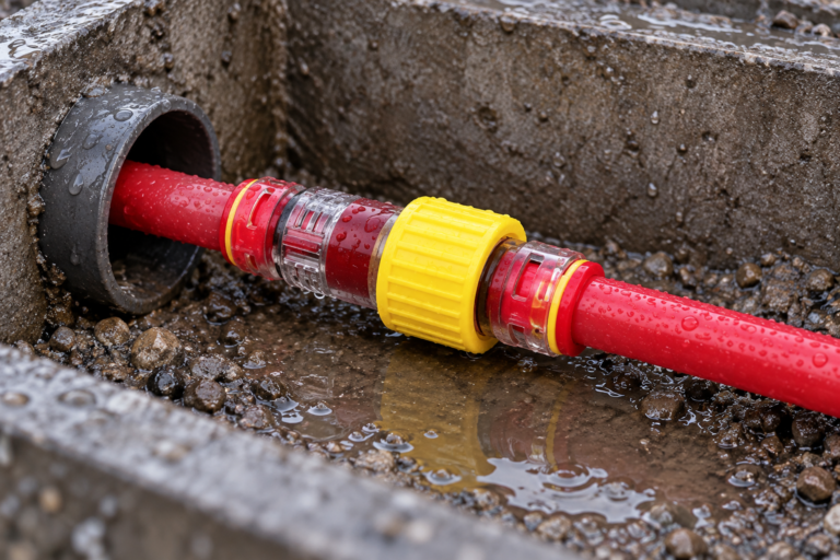
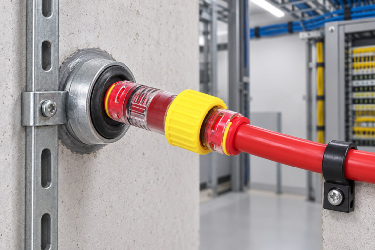
A Straight Micro Duct Connector is a straight-through, usually push-fit fitting with the same connection size on both ends. It uses a gripping mechanism and seal to retain two ducts on one axis. Its job is deliberately narrow: maintain continuity of a microduct route while minimizing steps, leakage paths, and internal disturbance that can increase blowing resistance.
Coupler is a purchasing term rather than one fixed geometry. A supplier may use it for a straight union, but the word can also describe a reducer, threaded transition, repair fitting, or fitting intended for a different pneumatic service. That distinction matters in FTTx and telecom ducts: a fitting that joins tubing physically is not automatically suitable for the route pressure, pull load, burial environment, or fiber-blowing method specified for the project.
For a 12/10 mm microduct, “12” commonly denotes the OD and “10” the approximate ID, leaving a nominal 1 mm wall. The actual duct and fitting data sheets govern tolerances. Do not infer that every 12 mm duct fits every 12 mm connector; ovality, wall thickness, polymer grade, and manufacturer tolerances affect seal engagement.
Straight connector vs. generic coupler: performance and total cost
| Чечим фактору | Microduct straight connector | Generic or non-specialist coupler |
|---|---|---|
| Primary use | Same-size, in-line microduct joint | May cover many tube or pipe joining duties |
| Бордун үзгүлтүксүздүгү | Designed to align compatible duct ends | Must be verified; a step or restriction may remain |
| Air-loss control | Seal and retention system selected for the duct application | Depends on the exact model, seals, and pressure rating |
| Fiber blowing impact | Lower risk when size, cut, and insertion are correct | Higher verification burden where geometry is unknown |
| Compatibility | Usually stated by OD range and duct material | May be limited to another tube standard or wall range |
| Бирдик чыгымдардын тенденциясы | Specialized, application-specific component | May appear cheaper, but varies greatly |
| Maintenance/TCO | Predictable when documented and pressure-tested | Potential rework cost if leakage or bore mismatch is discovered late |
The hidden cost is downtime, not only the fitting price. An illustrative example: if a two-person crew spends 45 minutes tracing one leaking joint, the cost includes labor, compressor time, rescheduled blowing, and the risk of cable damage—not just one replacement connector. A suitable Micro Duct Straight Connector that is installed once and verified can reduce that exposure. This is not a claim that every specialized fitting performs identically; it is a reason to compare the documented joint, installation method, and acceptance test together.
Use a microduct connector size guide before you order
Build the bill of materials from the duct OD, then confirm the fitting’s permitted wall-thickness and material range. Measure field duct with a suitable caliper at several orientations if it has been stored on a reel, exposed to heat, or cut from an unknown batch. A connector’s transparent body, where supplied, can help confirm insertion; it does not replace dimensional verification.
| Common duct marking | Номиналдык тышкы диаметр × ички диаметр | Nominal wall (calculated) | Typical straight-connector selection question |
|---|---|---|---|
| 5/3,5 мм | 5 × 3,5 мм | 0,75 мм | Is the fitting rated for 5 mm OD and this wall range? |
| 7/5,5 мм | 7 × 5,5 мм | 0,75 мм | Are both ducts the same OD and suitable material? |
| 10/8 мм | 10 × 8 мм | 1,0 мм | Does the fitting’s insertion depth clear the cut end? |
| 12/10 мм | 12 × 10 мм | 1,0 мм | Does the assembly specification call for a straight union or a reducer? |
| 14/10 мм | 14 × 10 мм | 2,0 мм | Is the larger wall thickness inside the connector’s approved range? |
The wall figures above are simple nominal calculations: (OD − ID) ÷ 2. They are not manufacturing tolerances or connector approvals. When two ducts have different ODs, use a purpose-designed reducing connector; when their ODs match but wall thickness differs, obtain the fitting manufacturer’s compatibility confirmation. For context on the role of fitting geometry in the route, see this guide to microduct fittings in fiber optic installations.
Prepare HDPE duct and prove the joint before fiber blowing
Cut, clean, inspect, insert
Cut each HDPE duct squarely with the correct cutter; remove burrs and avoid crushing the bore. Wipe away dust, moisture, and loose swarf, then inspect for deep scoring or an oval end. Push the duct straight into the fitting to its positive stop—do not twist it in a way that may damage the seal. Where a transparent body or witness window is provided, visually confirm that both duct ends have passed the indicated seating position.
Pressure and leak testing steps
- Isolate the tested duct section and fit approved test end closures.
- Pressurize with clean, dry air to the project or manufacturer-specified test pressure; never substitute a pressure value from another product.
- Allow temperature stabilization, then record starting pressure, time, ambient conditions, and test length.
- Hold for the specified period, inspect joints with an approved leak-detection method, and investigate any pressure decay beyond the acceptance criterion.
- Depressurize safely, document the result, and only then release the section for fiber blowing.
Air loss reduces the pressure available to propel cable and can make a route appear difficult when the real fault is a joint. The air-blown optical cable installation overview is a useful companion for planning the blowing phase, while this HDPE microduct installation and maintenance guide helps teams avoid upstream duct damage.
Standards, claims, and procurement controls
IEC 60794-5-20 covers outdoor microduct systems for blown optical fibre cables and is useful when specifying the duct-system context. IEC 61300-2-34 is a test method for resistance of fibre-optic interconnecting devices to air pressure; a test method is not, by itself, a blanket certification of a connector. EN 61386 addresses conduit systems for cable management and may be relevant where the installed duct system falls within its scope. National construction rules, client specifications, and utility-owner requirements remain controlling.
For procurement, request the connector data sheet, applicable test reports, approved duct OD/material range, operating-temperature range, insertion-depth information, and any pressure-test conditions. Avoid marketing claims such as “leak-proof” unless they state the tested configuration and conditions. Unsupported claims can create acceptance disputes, warranty uncertainty, and delayed handover—especially where FTTx contractors, network owners, and distributors share responsibility.
How to select the right in-line fitting for an FTTx project
- Map every joint by duct OD, ID, wall thickness, material, and route location; treat unknown duct as a compatibility risk.
- Choose a straight microduct connector for like-for-like in-line joints; specify a reducer or transition fitting when dimensions or systems differ.
- Set an installation acceptance process: square cut, clean bore, full insertion, visual check, and documented pressure test.
- Confirm temperature, UV, burial, and enclosure conditions against the exact product documentation rather than assuming a generic coupler is equivalent.
Microduct Connector can help buyers align configurable microduct fittings with duct dimensions, application information, and documentation requests. Ask for confirmation against your actual duct and test requirements before placing a project order.
Көп берилүүчү суроолор
Why does the microduct straight connector leak during or after fiber blowing?
Common causes are an out-of-square cut, burrs, dirt on the duct, incomplete insertion, a damaged seal, or a duct OD outside the fitting’s approved range. Isolate and test the section rather than increasing blower pressure; remove the duct only according to the fitting instructions, inspect the end and seal, then rebuild and retest.
Do you need tools or lubricant to fit the microduct straight connector correctly?
Most push-fit designs are intended to be installed by hand after a proper square cut and cleaning, but the exact product instructions control. Do not use lubricant unless the connector and duct manufacturer explicitly permit it, because an unsuitable compound can affect grip, sealing, or contamination control.
How can the microduct straight connector join ducts with different wall thicknesses?
Equal OD does not guarantee equal compatibility. Check the connector’s approved wall-thickness range and duct material; if the two ducts have different ODs, use a specified reducing connector instead of forcing a straight fitting onto an oversized or undersized duct.
What temperature range should the microduct straight connector withstand?
The required range comes from the route environment—outdoor exposure, enclosure temperature, transport, and installation conditions—and must match the specific product data sheet. Buyers should request the stated operating and installation temperature limits rather than applying a generic plastics temperature range.
How can installers visually check that the microduct straight connector is fully seated?
Use the fitting’s visible insertion mark, transparent body, or inspection window when provided, and verify that the duct end reaches the stated stop. A visual check supports, but does not replace, a pressure-hold test because a seated-looking duct can still have a damaged end or incompatible diameter.
When should the seals or body of the microduct straight connector be replaced?
Replace the affected component when inspection or testing finds a cracked body, damaged collet, nicked or displaced seal, persistent leakage, or a duct release that does not meet the manufacturer’s instructions. Do not reuse a fitting after a removal event unless its documentation specifically permits reuse and the sealing parts have been assessed.
Деректер
- IEC 60794-5-20: Оптикалык була кабелдери — үрүлгөн оптикалык була кабелдери үчүн ачык микротрубка системалары.
- IEC 61300-2-34: Жарык өткөрүүчү талча туташтыргыч түзүлүштөр жана пассивдүү компоненттер — Сыноолор — Аба басымына туруктуулук.
- ITU-T L.87: Оптикалык була кабелдик тармактар үчүн талаптар.
- EN 61386-1: Conduit systems for cable management—General requirements.
A straight joint should disappear from the project conversation because it has been specified, installed, and tested correctly—not because it was assumed to be “just a coupler.” For product selection or a compatibility review, explore Microduct Connector компаниясынын микродукт туташтыргычтарынын ассортименти жана Команда менен байланышыңыз with your duct dimensions and project test criteria.