
A connector ordered by nominal duct size can still be unsuitable for the assembled route. Procurement teams need to compare the actual outside diameter, the bore available for the cable, the wall construction and the installation environment, not just a catalogue pressure column. A tube may be retained before it is fully seated, while two ducts with the same outside diameter can have different internal diameters. Either detail can turn a seemingly straightforward purchase into additional installation checks or rework. This guide explains how to compare straight connectors, reducers and sealing functions, interpret pressure claims, and prepare an acceptance record that lets engineering and installation teams approve the same assembly.
The short answer is to select a microduct push-fit connector against the exact duct and connector drawings, then verify its intended environment and test conditions. Straight connectors join compatible equal-OD ducts; reducers accommodate different outside diameters but introduce a bore transition that may affect cable installation. EN 50411-2-8:2009 covers installed blown-fibre microduct connectors in protected installations, not connectors intended for direct sunlight. Working pressure, proof pressure and cable-sealing pressure are different claims. Before ordering, obtain the port ranges, compatible wall constructions, assembly instructions and an agreed route acceptance procedure rather than treating one headline rating as sufficient.
Which connector type matches the duct size and application?
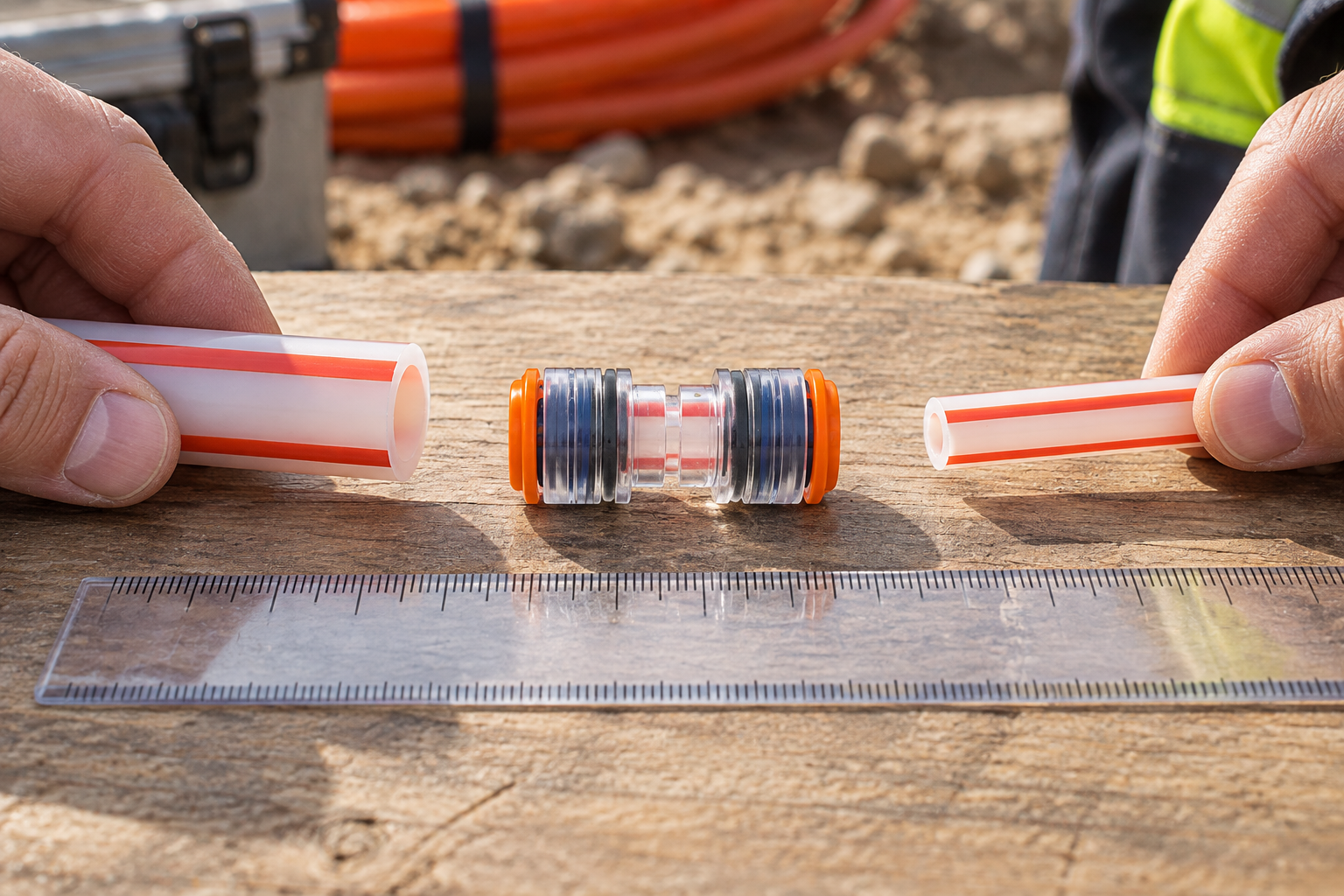
Compare by function before price. This selection framework distinguishes joining, transition and sealing tasks; it is not a model-specific performance ranking.
| Option or condition | Intended task | Evidence needed before selection |
|---|---|---|
| Straight push-fit connector | Join compatible equal-OD ducts | Port range, wall compatibility and assembly drawing |
| Reducer or enlarger | Join different duct sizes | Both port specifications and cable passage at the transition |
| Same OD, different ID | Join ducts with different bores | Approved wall constructions and smallest available cable passage |
| Vacant duct closure | Close an unused duct end | Compatible end cap and specified acceptance method |
| Occupied cable sealing | Seal the annulus around a cable | Cable OD, seal range and sealing-state pressure evidence |
그 straight microduct connector range does not approve every tube with the same nominal label. Duct diameter alone does not establish an indoor, drop or branch application.
Can ducts with the same outside diameter have different compatibility?
Yes: same OD does not mean same bore. Different wall thicknesses can leave different IDs even when both ducts appear to fit the same connector port. OD governs the external interface; ID affects the available cable path. Neither measurement independently confirms that the connector is approved for the tube’s wall construction.
Record each duct’s specified OD, measured condition, ID and wall designation against the connector drawing. Check roundness and surface condition using the manufacturer’s acceptance instructions. Do not force an out-of-range tube into a fitting or assume successful insertion proves compatibility.
A 레덕터 커넥터 also needs an installation check beyond its two port sizes. The official NEN catalogue scope for EN 50411-2-8:2009 notes that reducer or enlarger transitions may need manual feeding because of the pressure gradient at the size step. Confirm the cable route and feeding method before treating a reducer as an uninterrupted blowing path.
Which pressure rating should a buyer compare?
Compare like with like because pressure ratings describe different states. Record the assembly, medium, temperature, duration and acceptance criteria. These categories do not supply universal test values.
| Pressure category | What it addresses | What it does not establish |
|---|---|---|
| 작업 압력 | Permitted service conditions for the specified assembly | Approval of a different duct, seal or environment |
| 내압시험 압력 | Survival of a defined verification test | Continuous operation at that test pressure |
| Burst pressure | Failure threshold under stated test conditions | A permissible operating or field acceptance pressure |
| Cable-seal pressure | Sealing around the specified cable in the sealing state | Performance of the open blowing configuration |
| Route acceptance pressure | Acceptance of the installed pathway under the project procedure | Qualification of every component or future assembly change |
그 Waterproof Air Gas Block product page lists 10 bar blowing pressure and cable-sealing pressure up to 0.3 bar. It describes opening for blowing and rotating the ring to seal. These function-specific ratings are not interchangeable. Confirm the exact cable and duct combination from its drawing; do not test the cable seal at the blowing-pressure value.
How should installation and environmental evidence be checked?
그 FCST installation instruction, published 22 August 2025, gives a useful external manufacturer example: inspect duct dimensions and ovality, make a square cut, remove burrs and keep the tube clean and undamaged. It warns that a tube can be gripped without being fully seated, causing leakage. Apply the selected maker’s instructions rather than copying another manufacturer’s tolerances.
Where specified, fit the correct clip to prevent accidental release. A clip cannot correct wrong OD, a bad cut, a cracked body or a damaged seal. Depressurize before disconnection and follow the prescribed release sequence. If leakage occurs, isolate interfaces and check seating, dimensions, contamination and damage before assigning the fault to the connector.
EN 50411-2-8 addresses protected installations, including the underground and aerial environments described in its scope, and excludes connectors intended for direct sunlight. Its catalogue entry is not certification of an individual product. The IEC 60794-5:2014 catalogue covers microduct cables, fibre units, ducts and protected ducts for blowing installations; that broader cabling scope does not replace connector-specific evidence.
For exposed or buried routes, request exact-model environmental and mechanical evidence. An IP rating alone is not complete direct-burial qualification, and a cover shell is not automatically a pressure or gas seal. Do not convert accelerated UV exposure hours into a promised number of service years. Set inspection intervals from the approved maintenance plan and actual conditions, not a universal annual rule.
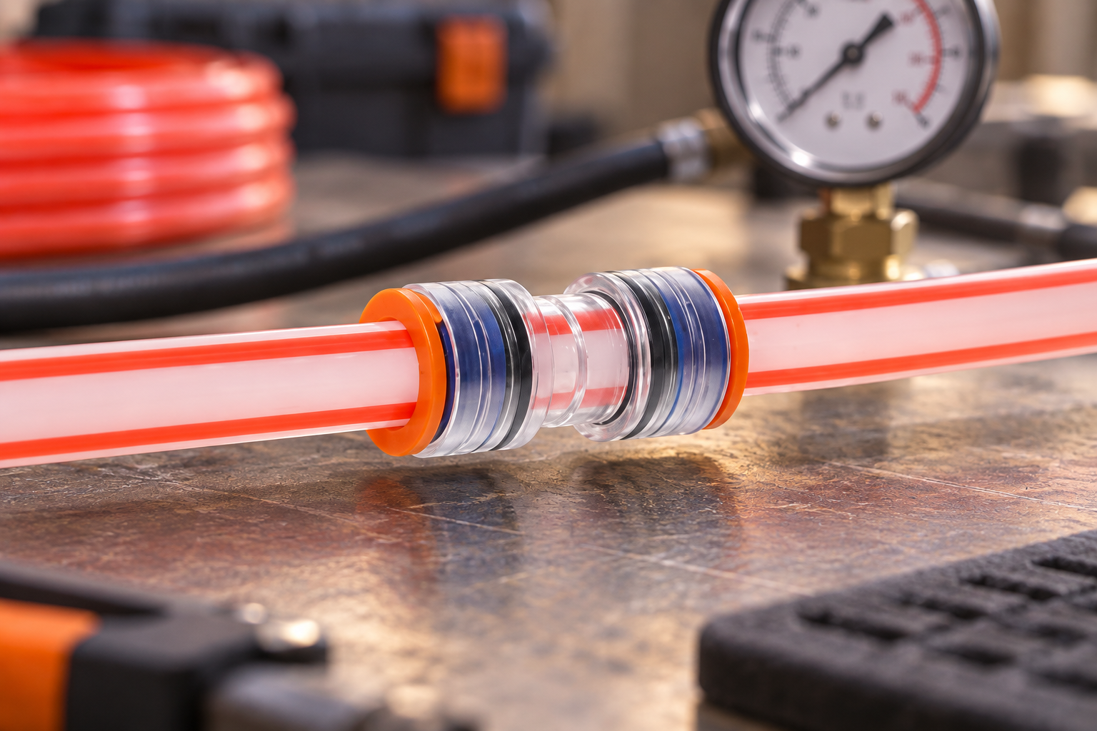
What should the buying and acceptance worksheet contain?
For an Oulu / ANMASPC enquiry, supply the duct pairing and assembly state. This practical worksheet is not a mandatory standard form; agree rejection criteria before ordering.
| 기록 | Acceptance question |
|---|---|
| Model, drawing revision and lot or production code | Can the delivered component be traced to the approved specification? |
| Duct OD, ID, wall designation and duct batch | Are both duct ends within the approved geometry and construction? |
| Cable OD and seal range, if occupied | Does the selected seal cover this actual cable? |
| Seating evidence, clip and assembly state | Was the joint assembled as instructed? |
| Medium, procedure, instrument and test conditions | Is the result comparable with the agreed acceptance requirement? |
| Result, correction and retest | Were deviations resolved before handover? |
Compare lead time and spare availability separately. Ambiguous drawings and untraceable substitutions can erase unit-price savings through rework.
What else should buyers ask about push-fit connectors?
Can a microduct push-fit connector be reused after the duct is disconnected?
Only with the exact manufacturer’s approval, inspection and the required retest. There is no universal reuse count; damaged or unsuitable components should not be reinstalled.
Which material and UV rating are best for outdoor microduct push-fit connector applications?
There is no universally best material. Obtain documented suitability for the intended exposure, body and seal, including temperature limits; a material name or unsupported UV-resistant label is insufficient.
Why does a microduct push-fit connector leak during or after fibre blowing?
Check wrong OD, incomplete seating, contamination, cut quality, damage and side-load. Isolate the joint from the rest of the pathway and repeat the approved test after correction.
Do you need tools or lubricant to fit a microduct push-fit connector correctly?
Use the preparation and inspection tools specified by the maker. Do not assume lubricant is required; use it only when the connector and duct instructions approve the product and application.
How can a microduct push-fit connector join ducts with different wall thicknesses?
Check OD and approved wall constructions independently. Equal OD may permit a straight connector, subject to approval; different OD needs a compatible transition, while either pairing requires an ID and cable-passage check.
What temperature range should a microduct push-fit connector withstand?
Use the installation and operating limits for the exact assembly. Do not infer them from HDPE resin data or a different connector model.
Does an empty-duct pressure test prove the cable seal is acceptable?
No. An occupied cable annulus needs its own compatible seal and applicable acceptance procedure. The 엔드 스톱 대 가스 블록 비교 explains the different closure tasks.
Does a wet connector prove that water entered through that joint?
No. Investigate the pathway and isolate potential interfaces; visible water does not identify its entry point. Record the diagnosis before replacing or resealing components.
Which primary sources support these comparisons?
- NEN: EN 50411-2-8:2009 connector scope and transition limitations.
- FCST: Microduct Connector Installation Instruction, 22 August 2025.
- IEC: 60794-5:2014 microduct cabling for installation by blowing.
How can buyers make a defensible connector selection?
The sound comparison is between documented assemblies, not isolated size labels or the largest pressure number. First establish the duct OD, ID, wall construction and cable path; then choose the joint or sealing function and verify the environment. A reducer needs a feeding-method decision, while an occupied cable seal needs evidence separate from the blowing state. Before delivery, agree the installation instructions and acceptance procedure, and retain the lot, dimensions, assembly state and test result together. Do not let a successful insertion or a proof-pressure claim replace those checks. Oulu / ANMASPC’s microduct product catalogue provides options for a specification-led enquiry; request the exact drawing and supporting conditions before approving a substitution or volume purchase.


