A solenoid valve converts an electrical command into a change in a fluid path. Selecting one requires more than the port size or coil voltage: the rest state, operating pressure, medium, flow demand and actuation design must fit the circuit. When a valve clicks but produces no useful flow, those same details provide a better starting point than replacing it by appearance.
A solenoid valve uses an electrically energized coil to move an armature or pilot mechanism and change a fluid path. A normally closed (NC) 2/2 valve typically blocks flow without power; a normally open (NO) version typically passes it. A 3/2 valve instead switches among three ports and two positions, so its port diagram matters more than the name. Specify the unpowered state, media, operating pressure range including minimum differential, voltage, duty, and connections from the exact datasheet before ordering.
How the Coil Moves the Valve and Changes Its Flow Path
In a common direct-acting design, current through the coil creates a magnetic field that pulls a movable armature against a spring. The movement lifts or seats a sealing element; removing power lets the spring return it. This explains the solenoid valve working principle, but does not mean every valve has the same internal layout. A pilot-operated design uses a small solenoid-controlled passage and the process pressure to move a larger main seal, so its stated minimum pressure differential may be essential. Bürkert’s Type 6013 is an example of a direct-acting 2/2 plunger valve, while Type 0330 shows that a direct-acting pivoted-armature family can include both 2/2 and 3/2 variants.
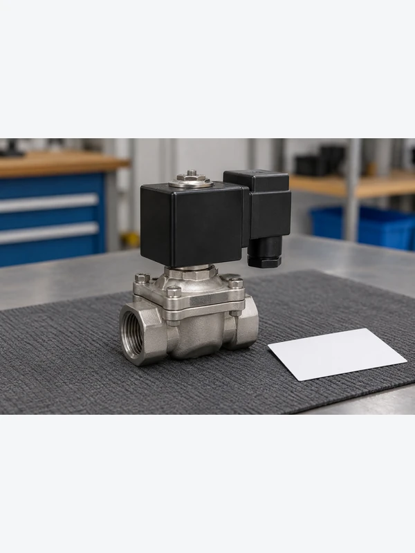
The notation counts ports first and switching positions second: 2/2 has two ports and two positions; 3/2 has three ports and two positions. It does not describe coil voltage, flow capacity, material, or fail position. A pneumatic 3/2 circuit may connect supply to an outlet in one position and the outlet to exhaust in the other. Confirm the actual P, A, and R or numbered port assignments on the manufacturer’s symbol and the marked body; do not infer them from fitting shape. For the port-state question, see the two-position three-way pneumatic valve principle.
Compare Normally Closed and Normally Open Rest States
For a 2/2 normally closed valve, the resting state blocks the designated flow path and energizing the coil opens it. A normally open 2/2 valve does the reverse. The choice is a control and risk decision: determine what the process must do on power loss, and assess the consequences of unintended flow, trapped pressure, or lost actuation. “Normally closed” alone is not a safety certification, isolation guarantee, or statement about allowable backpressure.
For 3/2 valves, NC and NO need a stated reference flow path, commonly supply to outlet, because another connection can be open while that path is closed. A spring-return valve has a defined unpowered position; a latching or double-solenoid arrangement may retain its last state. Check the symbol and state table rather than translating a 2/2 rule to a different circuit. The solenoid valve classifications overview provides related terminology, but the selected model’s drawing controls installation.
| Question | Direct-acting valve | Pilot-operated valve |
|---|---|---|
| What moves the main seal? | Magnetic actuation moves the armature and sealing element directly. | A solenoid-controlled pilot path uses process pressure to assist main-seal movement. |
| Low or zero differential | Some models are specified to operate at zero differential; verify the actual range. | Many designs require a minimum differential; confirm the exact model and flow direction. |
| Flow and size | Compare the documented orifice and flow coefficient, not the label alone. | Can address larger flow requirements where the specified differential is available. |
| Installation and upkeep | Check media cleanliness, seat compatibility, coil duty, and service access. | Also check pilot passages, filters where specified, and pressure during every operating state. |
| Cost exposure | A low unit price can be outweighed by incorrect sizing or coil replacement. | A mismatch at low differential can cause downtime even when the rated maximum pressure looks adequate. |
Match Fluid, Pressure, Flow, and Coil Requirements
Start with the medium: compressed air, water, oil, steam, or another fluid changes the acceptable body, seal, temperature, and contamination requirements. Then capture minimum and maximum inlet pressure, outlet/backpressure, differential across the valve during switching, flow demand, ambient temperature, and required leak behavior. The supplier’s pressure rating is not a promise that every pilot design works from zero pressure. Compare the manufacturer’s flow coefficient or characteristic at the intended conditions; nominal thread size is not a substitute for sizing.
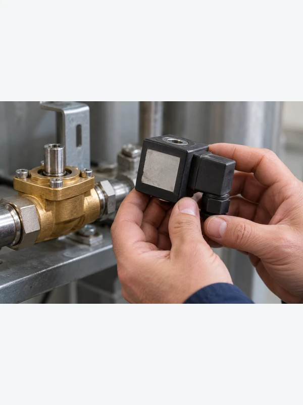
Next check electrical supply, AC or DC, rated voltage and permitted tolerance, power consumption, connector and enclosure, expected energized duration, and switching frequency against the exact coil data. Do not reuse an unsupported universal voltage tolerance or mounting rule. Confirm the flow arrow, permitted orientation, and manual override in the model instructions; isolate electrical power and depressurize the circuit before service. A system quote should include valve, compatible coil and connector, fittings, filtration if specified, commissioning, expected maintenance, and the cost of downtime or rework. There is no defensible universal payback figure without the site’s duty cycle and failure costs.
Measure the pressure available across the valve
The pressure difference available to a valve is the inlet pressure minus the outlet pressure in the relevant operating condition. A supply gauge alone cannot establish that differential. If the downstream side is already pressurized, or the inlet pressure falls during a demand event, the available difference may be smaller than expected. Review both sides of the valve during startup, switching, normal flow and shutdown.
For internally piloted designs, the required pressure conditions help generate the force that operates the main stage. Tameson’s guide to 3/2 pneumatic valves distinguishes direct, internal-pilot and external-pilot arrangements. The model’s specified limits control selection; do not copy a generic minimum differential from a different valve type. Likewise, a direct-acting label does not remove the need to check maximum pressure, flow capacity and media limits.
If the application starts with no line pressure or uses vacuum, identify a model explicitly intended for that condition. An external pilot is a separate specified configuration, not an improvised connection. Review the ប្រភេទផ្នែក pneumatic for the surrounding connections and controls, while obtaining the valve manufacturer’s circuit and pressure data for the exact variant.
Check Electrical and Pressure Conditions Before Replacing the Valve
Observe the commanded state, supply pressure, downstream response, and electrical signal without bypassing site safety procedures. A coil click is evidence of movement or magnetic action, not proof of adequate flow; no click does not by itself prove a failed coil. Use the manufacturer’s wiring and resistance guidance and the circuit diagram to separate electrical, pressure, and downstream faults. Record the valve part number and configuration before changing parts.
| រោគសញ្ញាដែលបានសង្កេតឃើញ | Check first | What the result can distinguish |
|---|---|---|
| No audible or visible change on command | Measure supply at the coil terminals under command, then compare coil and connector with the part-number data. | Missing control power, wiring error, or an electrical component fault; sound alone is inconclusive. |
| Actuation occurs but flow is absent or weak | Verify inlet pressure, outlet restriction, direction, filter condition, and minimum differential. | An upstream, downstream, or pilot-pressure problem rather than an assumed coil failure. |
| Wrong state when power is removed | Compare the specified NC/NO or 3/2 state diagram with actual port piping. | Selection or port-assignment mismatch; do not swap tubing without tracing the circuit. |
| Leakage or intermittent switching | Check approved media, contamination controls, pressure and temperature limits, and service instructions. | Seat contamination, out-of-range operation, or wear requiring model-specific inspection. |
Separate a switching sound from evidence of useful flow
A click tells the investigator that something changed at the energized assembly; it does not establish full main-stage travel or adequate flow at the load. First confirm that the commanded signal reaches the correct coil and matches its AC or DC specification. Electrical measurements should be made by a qualified person using the approved procedure. Record voltage under the relevant command, not just the controller’s displayed output state.
Next compare supply and downstream pressures with the expected flow state. Check isolation valves, filtration where specified, flow direction, pilot supply and the downstream load. On a pneumatic circuit, an exhaust restriction can prevent the expected actuator response even though the supply path changes. Investigate without bypassing guards or treating a manual override as a substitute for an isolation procedure.
Connection faults can coexist with a functioning valve. The pneumatic straight-fitting troubleshooting guide covers tube and joint issues that should be checked separately. A leaking tube, incorrect port adapter or kinked line cannot be diagnosed from coil sound. Identify each interface before deciding that the valve body or electrical coil needs replacement.
If service is permitted, isolate electrical power, release stored pressure and follow the model’s maintenance instructions before opening the assembly. Retain the original symptom, measured conditions, component identity and corrective action. After repair, test the commanded and rest states under the approved commissioning procedure. This provides evidence of the result rather than relying on the absence of an audible fault.
Read Valve Symbols and Verify Product Claims
ISO 1219-1 sets graphical-symbol rules for fluid-power systems and components; it helps communicate positions, ports, and actuation in a circuit drawing. It is not a certificate that a particular valve is suitable for a pressure, fluid, hazardous area, or safety function. The actual datasheet and applicable destination-market rules govern those claims. If a project requires a particular electrical approval, pressure-equipment conformity, ingress protection, or hygienic suitability, request the model-specific evidence and check the intended installation conditions before repeating the claim in a purchase specification.
For procurement, send the supplier five items: the circuit symbol and required unpowered state; media and temperature; pressure and flow at every operating state; power supply and duty; and port/tube dimensions plus environment. Ask for the exact model’s drawing, performance data, and installation instructions. In a pneumatic assembly, pneumatic coupling applications also affect tubing fit and serviceability, but a fitting specification cannot verify the solenoid valve mechanism.
សំណួរដែលសួរញឹកញាប់
What is a solenoid valve used for?
It switches a specified fluid path in response to an electrical command, commonly in pneumatic, hydraulic, water, or process-control circuits. The medium and use case must fall within the selected model’s published limits.
How does a solenoid valve work when power is removed?
A spring-return design moves to its defined rest position when the coil is de-energized. That may block, pass, or redirect a particular path depending on its NC/NO designation and port diagram; latching designs require separate interpretation.
What is the difference between a 2/2 and a 3/2 solenoid valve?
A 2/2 valve has two ports and two positions, usually switching one path. A 3/2 valve has three ports and two positions, often alternating an outlet between supply and exhaust; verify the actual symbol and port labels.
Can a pilot-operated valve work with no pressure?
Many conventional pilot-operated valves require a specified minimum pressure differential to switch reliably. Some assisted or special designs differ, so use the exact model’s operating-pressure range rather than a category-wide assumption.
Does a clicking coil prove the valve is working?
No. The sound does not establish adequate inlet pressure, an open flow path, clean pilot passages, or correct downstream operation. Check measured electrical and pneumatic conditions under the commanded state.
Can the pneumatic fitting shown here be used to identify a solenoid valve?
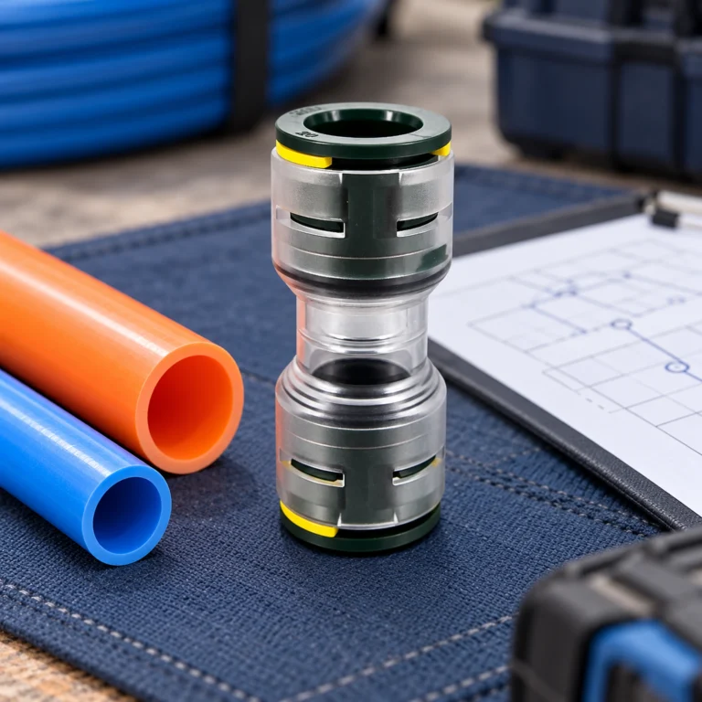
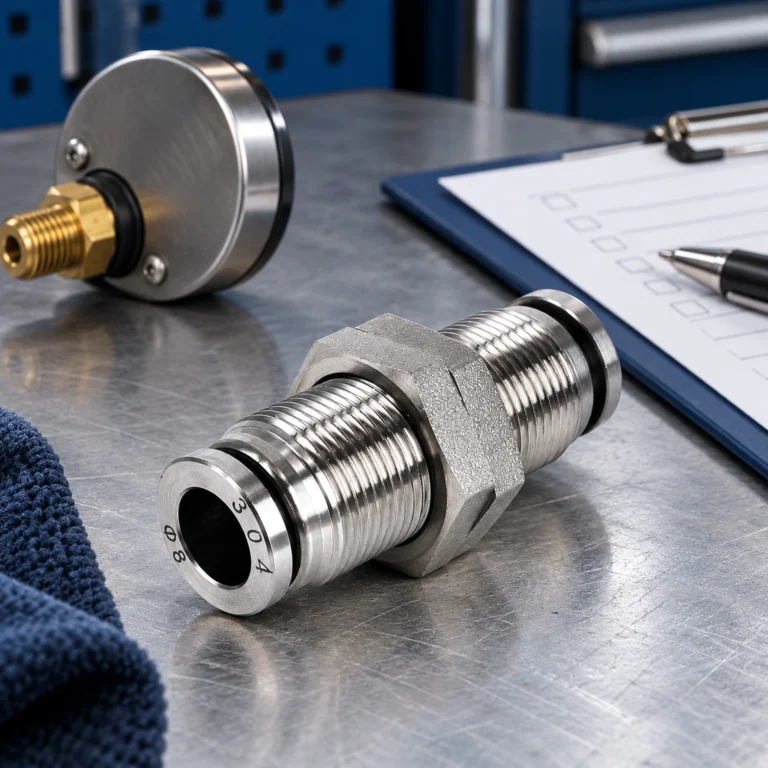
No. The S-VHK2 images show related pneumatic connection hardware, not a verified solenoid coil or internal valve section. Identify a solenoid valve by its model documentation, electrical specification, and circuit symbol, and specify fittings separately.
How much pressure can a solenoid valve handle?
There is no universal value. Use the exact model’s operating-pressure range for the specified medium and temperature, and check minimum differential, backpressure and flow direction where relevant. A maximum inlet rating alone does not establish whether a pilot-operated valve will switch in your circuit.
Why can a valve work at normal pressure but fail during startup?
Its internal pilot may not have the required pressure conditions while the system is being pressurized. Check the documented minimum supply or differential and any separate pilot requirement in the startup state. Also verify the command, port assignment and downstream restrictions before attributing the symptom to pilot pressure alone.
ឯកសារយោង
- ISO 1219-1, Fluid power systems and components: Graphical symbols and circuit diagrams, Part 1. Symbol scope, not product certification.
- Bürkert Type 6013 direct-acting 2/2 plunger valve. Manufacturer example of a direct-acting design.
- Bürkert Type 0330 direct-acting 2/2 or 3/2 pivoted-armature valve. Manufacturer example of distinct port configurations.
- Emerson ASCO valve resources. Manufacturer context for application-specific valve selection.
- Tameson: 3/2-Way Pneumatic Valves—Direct and Pilot Operation
Summary
Select a solenoid valve from the required flow states, medium, pressure conditions, flow demand and electrical duty. Verify how the chosen actuation design behaves during startup and loss of power or pressure. When troubleshooting, separate electrical command, pilot conditions, actual flow and downstream response; a click does not confirm all four. Keep the valve data and mating connection specification together, then document the final functional checks after any correction.