
When a field supervisor in Rotterdam encountered rapid pressure loss during an HDPE repair, the crew had already pushed a nominal 12 mm connector onto a duct with a different measured bore. The coupling looked seated, yet the first air check failed. This illustrative scenario reverses a common first diagnosis: the issue is not necessarily a bad product, but can be an incorrect size, specification or preparation process. Duct outside diameter, cut quality, seal condition and the test method all matter. This guide explains how to specify a Microduct Connector 12mm without treating a nominal size or generic pressure claim as universal.
Sintesi: Select a 12 mm connector against the exact HDPE duct drawing and verify it by a controlled leak test—not by its carton label. EN 50411-2-8 is a product-test framework, not automatic product certification. Confirm outside diameter and wall profile, make a square clean cut, check both ends at the inspection feature, and use the pressure, stabilisation time and acceptance limit in the product or project record. ITU-T L.108 addresses microduct-blowing installation application, while IEC 60794-5-20 covers blowable fibre-optic cabling.
Why a 12 mm Label Does Not Confirm Connector Compatibility
“12 mm” describes a duct family, but the interface still depends on the manufacturer’s drawing. Ducts with the same nominal label can differ in wall thickness, ovality or jacket construction. Record the duct material, measured outside diameter, tolerance and connector part number together. The page for a 12/10 mm HDPE microduct straight connector shows why the full designation matters: “12” and “10” are different dimensions, not interchangeable product families.
For fibre blowing, the joint must also preserve a continuous bore and limit avoidable air loss. ITU-T L.108 addresses the installation application for blowable optical-fibre cable elements; it supports documenting the route and test condition, not merely the fitting name.
Prepare HDPE Duct Ends Before Installing the Connector
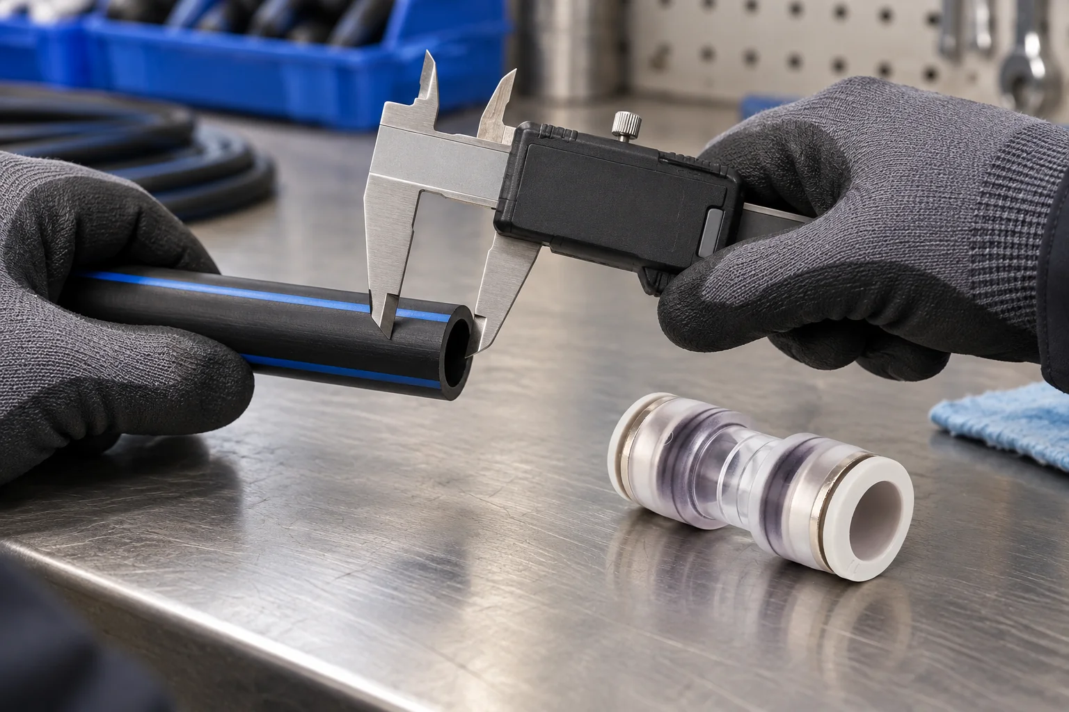
Cut both ducts square without crushing the wall, remove burrs and swarf, and wipe away grit, lubricant residue and moisture. If an end is ovalised, flattened or scored, cut back to sound material. A clean, perpendicular end makes a transparent body useful because the installer can see the intended stop rather than infer engagement from hand force.
Do not add thread tape to a push-fit interface or mix a reducer with a straight body because the diameter looks close. Protect seals and bodies from grit, and keep the exact installation drawing with the work pack.
How Connector Size Affects Air Loss
Use measured dimensions to separate three decisions: the duct-to-connector interface, the route application and the test boundary. A straight connector joins like-for-like ducts; a reducer is for a documented transition; an end stop closes an unused end. A Microduct Connector 14mm is not a safe substitute for a 12 mm interface because both parts are described as “microduct connectors.” Likewise, an 8mm Microduct Straight Connector belongs to a smaller duct family and should be specified only when the drawing confirms the matching bore and outside diameter.
| Option | Use when | Cosa verificare | Typical hidden cost if misapplied |
|---|---|---|---|
| 12/10 mm straight connector | Both ducts are the same documented family | Outside diameter, wall profile and insertion witness | Rework and blowing delay |
| 14mm Microduct Straight Connector | The route drawing specifies a matching 14 mm duct family | Actual interface and burial or chamber requirements | Wrong fit or damaged duct ends |
| 8mm Microduct Straight Connector | A smaller microduct is scheduled | Drawing, insertion depth and blowing equipment | Restricted bore or seal distortion |
| Reducer or transition body | The route changes duct size | Both interfaces and the test boundary | Pressure drop and extra inspection |
Check Connector Seating and Complete the Leak Test
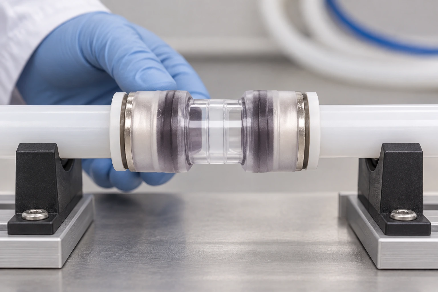
Check the transparent body or witness mark for full seating at both ports before applying pressure. Bound the test section with known closures, isolate branch paths and allow stabilisation. Use a calibrated instrument, then record the test medium, ambient condition, hold time, pressure change and result.
There is no universal pressure or hold time for every 12 mm connector. Use the connector drawing, duct specification and project method. If a test fails, isolate the section, inspect both witness positions and remake the cut before suspecting the body or seal. Never raise pressure when the permitted value is unknown.
Air loss consumes compressor capacity and can delay fibre movement. Total cost can include re-excavation, crew travel and a missed work window; any illustrative ROI calculation should use the project’s measured leak and labour rates.
Include These Application Details in the Purchase Order
Specify the environment alongside dimensions. Chamber, direct-buried, building-entry and temporary sections can require different bodies or closures. Hexatronic groups connectors and end stops as accessories, while Dura-Line lists micro-couplers within microaccessories; these are market examples, not proof of interchangeability.
| Purchase-order field | Evidence to attach | Decision it supports |
|---|---|---|
| Duct designation | Drawing and measured outside diameter | Interface and tolerance check |
| Connector function | Straight, reducer, end stop or block | Body geometry and route purpose |
| Ambiente | Chamber, direct-buried, indoor entry or temporary work section | Protection and maintenance assumptions |
| Test record | Method, gauge, hold time and acceptance limit | Repeatable sign-off |
| Traceability | Batch, drawing revision and seal reference | Controlled maintenance |
What the Relevant Standards Prove—and What They Do Not
EN 50411-2-8 provides a product-test framework for microduct connectors used with air-blown optical fibres. ITU-T L.108 covers microduct-blowing installation application, while IEC 60794-5-20:2014 covers outdoor microduct fibre units, microducts and protected microducts installed by blowing. These documents guide evidence requests; they do not replace a part drawing or test report.
Distinguish “tested to a method” from “certified” or “compliant.” Ask for the edition, scope, sample configuration and limits behind a declaration. Add any national, utility or environmental requirement to the purchase order. Unsupported IP, UV, pressure, temperature, lifetime or certification claims create approval risk even when a part fits.
Approve a 12 mm Connector with This Procurement Checklist
- Freeze the interface: match the drawing to measured outside diameter, wall profile and tolerance.
- Define the job: state whether the joint is straight, transitional, buried, chamber-based or temporary.
- Approve the method: attach the preparation, seating and pressure-test procedure; the size and air-leak selection guide provides a broader checklist.
- Control replacements: list seal and body references, batch traceability and replacement triggers.
- Review evidence: compare drawings, test reports and destination requirements before volume orders.
At this decision stage, Oulu / ANMASPC (Zhejiang Oulu Automatic Equipment Co., Ltd.) can be considered as a China-based B2B manufacturer of microduct connectors and pneumatic parts. Buyers should request the exact drawing and test record for their duct family. Its transparent-position-check microduct straight connector page illustrates visible seating inspection.
Frequently Asked Questions About 12 mm Microduct Connectors
How can installers visually check that the Microduct Connector 12mm is fully seated?
Use the body’s transparent section, witness line or specified insertion stop and confirm that the duct reaches the same position at both ports. Record the check before pressurising the test section; if the mark is not clear, depressurise and remake the cut rather than relying on hand force.
When should the seals or body of the Microduct Connector 12mm be replaced?
Replace a seal after visible damage, contamination, distortion or an unsuccessful remake that leaves the seal path uncertain. Replace the body when its ports, inspection window or locking features are cracked, deformed or outside the approved drawing; use the supplier’s replacement guidance for storage and batch traceability.
Where can installers use the Microduct Connector 12mm in fiber and telecom networks?
Typical uses include joining matching HDPE microducts in FTTH/FTTx routes, chamber repairs and controlled blowing sections. Suitability for direct burial, building entry or a gas/water-block duty depends on the exact body, duct system and project specification, so verify the application before installation.
How do you choose the correct duct diameter for the Microduct Connector 12mm?
Start with the duct manufacturer’s drawing and a field measurement of outside diameter, wall profile and tolerance. Then match both connector ports to the same documented interface; if the route changes size, select a specified reducer and test each boundary according to the approved method.
How do you install the Microduct Connector 12mm without causing an air leak?
Cut the HDPE square, remove burrs, clean and dry the ends, protect the seals, and insert each duct to the visible stop. Isolate the finished section and perform the project leak test before blowing fibre; do not add unapproved sealants or force a damaged duct end into place.
What pressure and time should be used to test the Microduct Connector 12mm?
Use the pressure, stabilisation period, hold time and acceptance limit stated in the connector documentation, duct specification or project method statement. Because these values are configuration- and project-dependent, a generic number could be unsafe or invalid; record the instrument and boundary with the result.
What to Confirm Before Ordering a 12 mm Connector
For a 12 mm connector, the decision starts with the manufacturer’s drawing and measured duct dimensions, then moves through function, route exposure, end preparation, visible seating and the project leak-test method. Standards provide installation context, but the exact part record and acceptance rule define what can be approved; a nominal size cannot fill those gaps. The 12.7 mm connector comparison is a useful cross-check on tolerance and transition questions, and the air-blown installation guide links the specification to field controls.
Riferimenti
- ITU-T, Recommendation L.108: Optical fibre cable elements for microduct blowing-installation application (2018): itu.int/epublications/publication/itu-t-l-108-2018-03-optical-fibre-cable-elements-for-microduct-blowing-installation-application.
- IEC, IEC 60794-5-20:2014, Optical fibre cables—Part 5-20: Family specification—Outdoor microduct fibre units, microducts and protected microducts for installation by blowing: webstore.iec.ch/en/publication/3509.
- CENELEC, EN 50411-2-8, Fibre organisers and closures to be used in optical fibre communication systems—Product specifications—Part 2-8: Microduct connectors for air-blown optical fibres (product-test framework; consult the licensed edition for requirements).
- Hexatronic Fiber Solutions, Microduct Connectors and End Stops: hexatronic.com product page.
- Dura-Line, Microaccessories—Micro-couplers: duraline.com microaccessories page.
The practical takeaway is simple: a 12 mm label starts the specification; it does not finish it. Match the measured duct to the manufacturer’s drawing, choose the correct straight, reducer or closure function, and record the seating and leak-test method before fibre blowing. If the drawing or acceptance limit is missing, pause the order and request it through the contact page with the relevant 12/10 mm product information in hand.


