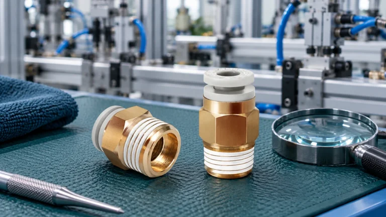
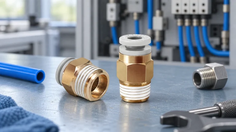
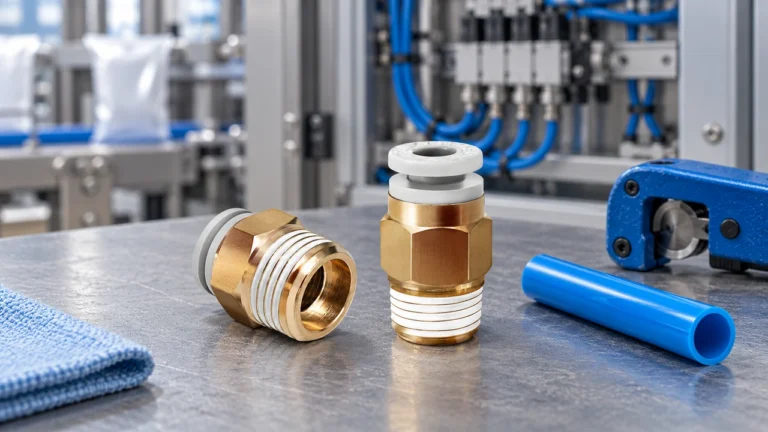
When a réseau installer in Oulu joined two microduct sections before a fiber-blowing run, she selected a connector by the nominal duct label and started the compressor. The pressure would not stabilize, and the cable stalled within minutes. The fitting was not automatically a bad part: the route had mixed duct outside diameters and an inadequately prepared cut end. Once the team checked dimensions, seating depth, and the planned test procedure, the installation could proceed.
Quick answer: Microduct fittings make an air-blown fiber route continuous, serviceable, and capable of being tested as an assembly. The decisive distinction is between a fitting’s duct outside-diameter interface and the duct’s inside diameter, which governs the passage available to a cable. IEC 60794-5-20 addresses microduct cabling intended for blowing, but it is not a blanket certification for every connector. Specify both duct dimensions, fitting function, environment, and project test conditions before purchase; then inspect and test each completed joint before blowing fiber.
Related reading: end-stop installation guide.
What a bad microduct joint does to fiber blowing
A microduct system is more than duct and cable. Straight connections extend a route; reducers bridge designed size changes; branch fittings organize distribution; end caps and plugs protect unused paths; and gas-blocking components can be specified where the network design calls for separation between sections. Each fitting changes the route’s geometry and can affect how readily installation air is retained and how smoothly a cable passes through.
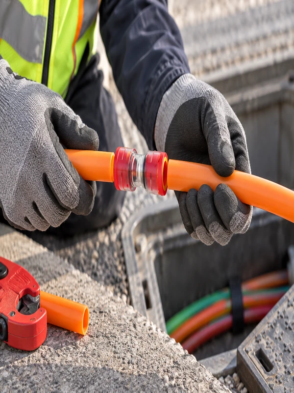
That makes fitting selection a total-cost decision. A low unit price can be outweighed by a halted blowing operation, cable recovery, or a missed construction window. Compare the cost of a documented joint with the cost of diagnosing an uncertain one after the route is closed.
| Fitting type | Primary role | Key procurement check | Route-risk to manage |
|---|---|---|---|
| Straight connector | Joins equal-size duct sections in line | Exact duct OD at both ends and insertion depth | Misalignment or a damaged duct end |
| Raccord de réduction | Connects two specified duct OD sizes | Each end’s size and the downstream cable route | An unintended restriction or wrong orientation |
| Branch or multiway fitting | Creates a planned distribution path | Port identification and access for future work | Confusing live and spare routes |
| Gas block, plug, or end cap | Closes or isolates a route where specified | Function, duct size, and installation location | Using a closure where a pass-through is required |
Which fitting do you need: straight, reducer, end stop, or gas block?
Start with the route drawing. A microduct connector category is useful for comparing forms, but the order line should identify the actual duct OD on every port. A straight connector is appropriate only when both duct ends match its stated interfaces. A straight microduct connector can keep an equal-size route simple when the cut is square, clean, and fully inserted.
Reducers deserve extra attention because the cable and airflow must negotiate the changed geometry. Confirm the designated small and large ends, the cable manufacturer’s route guidance, and whether the change is part of the engineered pathway. For a designed transition, compare the available microduct reducer connector configuration with the marked duct sizes; never treat near-matching metric and inch dimensions as interchangeable.
| Selection field | What to record | Why it matters |
|---|---|---|
| Duct interface | Manufacturer, nominal size, measured OD, and wall/ID | OD determines fitting compatibility; ID affects cable passage |
| Fitting function | Straight, reducer, branch, closure, or gas block | Prevents a route function being solved with the wrong component |
| Installation setting | Direct-buried, chamber, building entry, or indoor route | Guides access, protection, and project-specific requirements |
| Acceptance plan | Visual checks, test pressure, duration, and pass/fail rule | Makes site testing repeatable rather than subjective |
How to prepare and test a microduct joint
Prepare every duct end according to the fitting manufacturer’s instructions: cut squarely, remove debris, preserve the tube profile, and push it to the positive stop where applicable. A visible insertion mark can support inspection but does not replace a pull check or approved test procedure. Do not use unapproved lubricants, adhesives, or improvised sealing methods.
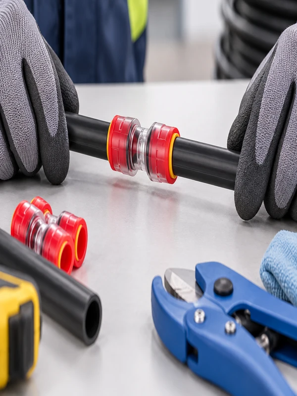
Before fiber blowing, isolate the section and use the project’s defined pressure-decay test or other documented air-tightness test. Record the section, test medium, stabilized pressure, duration, instrument, ambient conditions where relevant, and acceptance result. A pressure-decay test is a test method, not a universal product rating: the pressure and duration must come from the network specification and the applicable component documentation. Investigate a failed section systematically-duct end, seating, component damage, and test setup-rather than simply increasing pressure.
Standards support disciplined specifications, but their scope matters. IEC 60794-5-20 concerns microduct cabling designed for installation by blowing; IEC 60794-1-2 provides optical-fiber-cable test procedures; and ITU-T L.35 gives guidance on installing optical-fiber cable networks. These sources do not justify claiming that an individual fitting is certified, leak-proof, or suitable for every duty. Contract documents, destination-market requirements, and model-specific manufacturer data remain the basis for procurement and marketing claims.
What to confirm before ordering
- Map every joint to a route location and identify whether it must pass cable, change size, branch, or terminate a spare duct.
- Capture duct OD and ID from current manufacturer documentation; measure unmarked legacy duct rather than guessing from appearance.
- Request the exact fitting data, installation instructions, and compatibility information for the planned duct combination.
- Define the test record before crews arrive, including the test method and the person authorized to accept the section.
Oulu can be included early in a specification-led review of microduct gas-block options and related fitting configurations. The useful supplier conversation starts with duct dimensions, route purpose, installation conditions, and documentation needs-not a generic request for a connector.
Use one fitting function for each route problem
A route becomes easier to design when each fitting has one defined job. A straight connector joins equal-size ducts; a reducer handles a documented OD transition; an end stop closes an unused duct; and a gas-block design is selected when the project requires a tested air or water barrier. These names are not interchangeable. The duct outside diameter, bore continuity, pressure class and access condition should be written beside the fitting function on the schedule.
Related reading: microduct connector selection guide.
| Route situation | Starting fitting choice | Acceptance question |
|---|---|---|
| Same-size duct extension | Straight connector | Is the bore continuous and the seal seated? |
| Documented size transition | Réducteur | Does the drawing control the transition and both OD ranges? |
| Unused or staged duct | End stop or end cap | Can it be removed without damaging the duct? |
| Building entry or zone boundary | Gas-block connector where specified | What barrier test and pressure hold does the project require? |
For field preparation, link this decision to the end-stop sourcing guide and the microduct connector range. Standards such as IEC 60794-5 and EN/IEC product documents define scope and methods; they do not remove the need to follow the network owner’s acceptance plan.
What evidence should be complete before fiber enters a microduct?
Use a staged handover. First confirm the route drawing, duct identity, outside diameter and every joint or transition. Then check the cut, insertion, support, cleanliness and end protection. Finally run the project-approved continuity, proving or integrity check and record the equipment, medium, stabilization, criterion and result. ITU-T L.35 and L.87 provide optical-cable and outside-plant context, while IEC 60794-5-20 identifies a microduct-cabling scope; none replaces a route-specific acceptance method.
A passing pressure result does not prove that a bend, bore restriction or feed arrangement will accept the chosen fiber unit. If a blowing run stops, preserve the condition and isolate the nearest transition before replacing a connector. Compare the cable, duct and connector dimensions, then inspect bends and machine settings. This sequence produces evidence that distinguishes a joint problem from a route problem.
| Handover stage | Record | Decision |
|---|---|---|
| Before jointing | OD, wall, cut quality, route ID | Reject damaged or mismatched ends |
| After jointing | Part, insertion, alignment and support | Accept only the documented assembly |
| Before blowing | Continuity, obstruction, leakage and test result | Release the route or correct the boundary |
Foire aux questions
What fittings are used in microduct systems?
Common microduct-system fittings include straight connectors, reducers, branch fittings, end caps, plugs, and gas-blocking components. The required type depends on whether the route must continue, change duct size, distribute, or close a section; select by the documented network design and duct interfaces.
Why are microduct fittings important for fiber blowing?
Fittings join the duct path that carries installation air and guides the cable, so poor sizing or assembly can interrupt the planned blowing run. Their importance is practical: a properly specified and tested joint helps the team identify route issues before cable installation.
How do I choose a microduct connector size?
Match each connector port to the actual outside diameter of the duct it receives, then confirm the duct inside diameter supports the intended cable route. Use manufacturer data and measurements for existing duct; nominal labels alone may be incomplete or from different sizing systems.
Can microduct fittings be reused?
Reuse depends on the exact fitting design, its condition, and the manufacturer’s instructions. Inspect the body, retention elements, seals, and removed duct end; if damage, contamination, or uncertain retention is present, replace the component rather than relying on a reused joint.
How do I test a microduct connection for leaks?
Isolate the route section and perform the pressure-decay or other air-tightness test defined in the project specification. Log the setup and result, then correct the duct end, seating, component, or test arrangement indicated by the investigation before accepting the section.
What is the difference between a straight connector and a reducer?
A straight connector joins two duct ends with the same specified outside diameter. A reducer joins two different specified duct sizes, so its orientation and effect on the downstream cable path need to be checked during design and installation.
Related reading: Oulu Connector company information.
Références
- IEC 60794-5-20 – microduct cabling scope.
- ITU-T L.35 – optical fibre cable installation context.
- ITU-T L.87 – optical fibre cable maintenance context.
- Hexatronic duct-integrity testing guidance.
Summary
Microduct fittings protect a fiber route only when their function, dimensions and test method agree. Start with the route stage, measure the duct and match the connector, reducer, end stop or gas block to that state. Qualify the passage before introducing fiber and keep the test record with the route drawing. A pressure result alone does not prove bend suitability or cable-blowing success; investigate the nearest transition alongside geometry, obstruction and machine conditions. ITU and IEC documents frame the application, while the project procedure and product drawing define acceptance. Oulu’s microduct fitting range can be reviewed against the measured route and handover requirements.