
Pressure loss during fibre blowing is often blamed on the connector before anyone checks the cut, insertion depth, alignment, or part rating. That assumption creates repeated setup, wasted crew time, contamination, and an inconclusive leak search. The real question is whether the part matches both duct outside diameters and the environment, then was installed as documented. This guide gives buyers and installers a seven-step sequence, two selection tables, and acceptance evidence.
Sažetak: A reliable Air Blown Fiber Microduct Connector joint depends on seven controls: identify both ducts, isolate the work, cut square, clean and inspect, mark the documented insertion depth, seat and secure the ducts, then test using the connector manufacturer’s stated method. EN 50411-2-8 provides a product-specification framework for sealed air-blown-fibre microduct connectors, while IEC 60794-5-20 and ITU-T L.79 address the wider blown-fibre system context. None supplies a universal field pressure, hold time, temperature range, UV rating, or reuse rule. Obtain those values for the exact part number before work begins.
Check Both Duct Ends Before Installing the Connector
A microduct connector joins two duct ends so the cable-blowing air path can continue across the joint. Duct outside diameter, wall profile, surface condition, ovality, cut quality, loading, exposure, and connector design all influence the result. Nominal bore alone is not a safe sizing basis because push-fit connectors normally engage the duct’s outside surface.
“Airtight” also needs a defined test condition. Passing one installation test does not qualify a joint for every compressor setting, submerged location, temperature cycle, or outdoor exposure; a straight coupler is not automatically a gas-water block. The work pack should identify the duct pair, exact connector code, environment, and acceptance test.
Follow These Seven Steps to Install the Connector
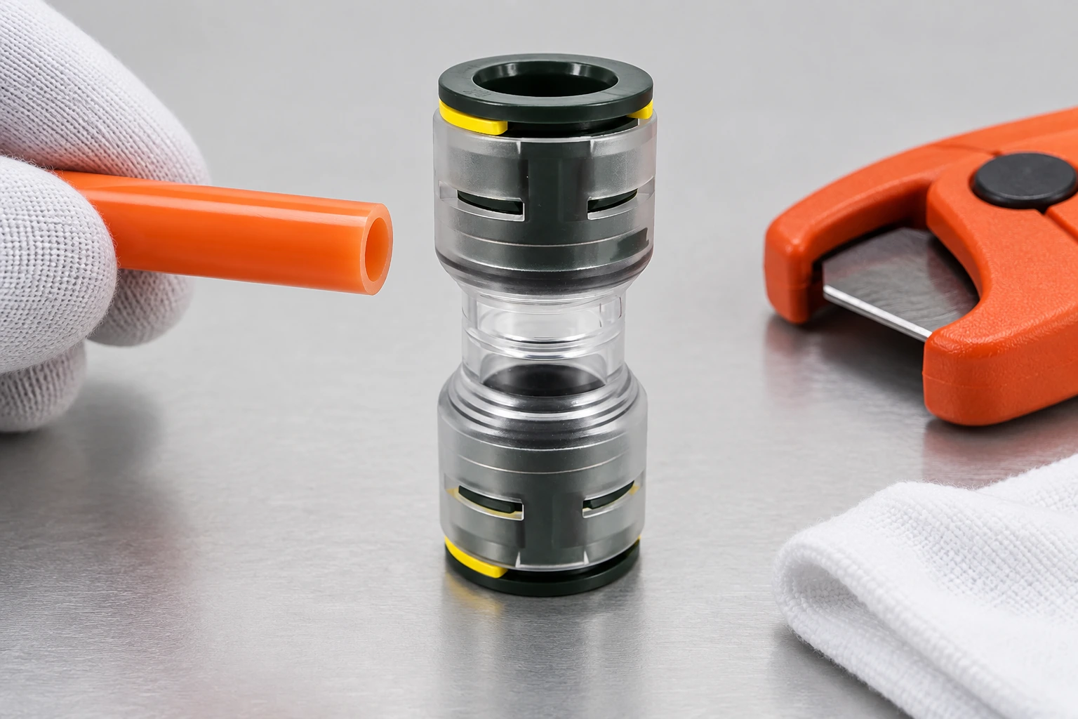
Step 1: Confirm both duct interfaces and the exact connector code
Read the marking and datasheet rather than selecting by appearance. Record both duct outside diameters, wall profiles, connector end sizes, location, and joint function. A 2 Way Air Blown Fibre Microduct Connector describes a two-ended connection but does not prove that both ends accept the same diameter. Confirm each duct’s outside diameter and insertion geometry in the exact connector documentation.
Step 2: Depressurize, isolate, and protect the open duct
Stop the equipment, isolate the air source, and verify that the duct is not pressurized. Follow site instructions for stored pressure and moving cable, and cap open ends against soil, water, or swarf. The guide to Ugradnja i održavanje HDPE mikrotubusa adds route context, but the connector instructions remain controlling.
Step 3: Make a square, controlled cut
Use a cutter recommended for the duct size. The cut should be square, round, and free from burrs, crushing, and loose fragments. Avoid debris-producing methods unless the documented process permits them. Do not improvise a chamfer; some designs require a preparation tool, while others specify a plain cut.
Step 4: Inspect and clean the sealing zone
Inspect the full insertion zone. Cut back past scoring, flattening, kinks, embedded dirt, or an out-of-round end that prevents uniform engagement. Clean by the approved lint-free method. Never apply grease, solvent, tape, sealant, or cable lubricant at the interface unless the exact instructions name it.
Step 5: Mark the documented insertion depth
Take the insertion depth from the drawing, gauge, or manufacturer instruction and mark each duct. Do not copy a dimension from a similar-looking connector. After assembly, the mark should show that the body reached the documented position.
Step 6: Insert, lock, and perform the specified retention check
Keep the duct and connector coaxial, then push each duct to its documented stop without side-loading. Fit clips, rings, or retainers only as specified. Perform a pull-back or other retention check only as instructed; excessive pulling cannot prove correct insertion.
Step 7: Support the joint and verify it under the approved test
Remove bending load and provide the required support or protection. Before blowing, test the isolated section by the approved procedure. Record medium, pressure, stabilization and hold time, temperature, leak method, result, part code, and installer. Never borrow pressure or time from another product or exceed the assembled system’s lowest documented limit.
Choose a Straight Connector, Reducer, or End Stop for the Job
| Connector function | Appropriate selection question | Evidence to verify | Common selection error |
|---|---|---|---|
| Straight connector | Are the two permitted duct outside diameters the same? | End sizes, insertion depth, pressure and environmental limits | Assuming one body fits every wall profile with the same nominal bore |
| Reducing connector | Does each end match its designated duct outside diameter? | End A/End B drawing and installation orientation, if any | Forcing a smaller or larger duct into a straight fitting |
| Gas-water block or sealing fitting | Must the interface limit migration around a duct or installed cable? | Use condition, size range, test method, and rating | Treating every blown-fibre coupler as a barrier seal |
| Repair or divisible connector | Must an existing occupied route be restored without feeding from an end? | Permitted repair geometry, assembly method, and final test | Using a part without a documented repair application |
Compare Connector Options by Fit, Function, and Documentation
| Decision dimension | Minimum buyer input | Supplier document to request | Field acceptance evidence |
|---|---|---|---|
| Duct fit | Both outside diameters, tolerances, and wall profiles | Exact-part dimensional drawing and compatibility statement | Part code, duct identity, insertion marks |
| Blowing conditions | Planned equipment and route operating envelope | Permitted pressure and test instructions for the exact part | Recorded pressure, time, temperature, method, and result |
| Outdoor or buried exposure | UV, water, soil, enclosure, and temperature conditions | Temperature, UV, and installation limits | Correct protection and location recorded before backfill or closure |
| Maintenance and reuse | Expected access and disconnection policy | Written release, inspection, replacement, and reuse rules | Traceable disposition: retained, replaced, or rejected |
| Total cost | Crew access, retest, reblow, and restoration exposure | Installation instructions and available quality records | Checklist and test record |
A poorly documented mismatch can add reopening, cleaning, retesting, blower remobilization, and delayed handover. Buyers evaluating Microduct Connectors For Air Blow Products should compare the document pack and installation method alongside unit price.
Use Standards as a Reference, Then Follow the Part Instructions
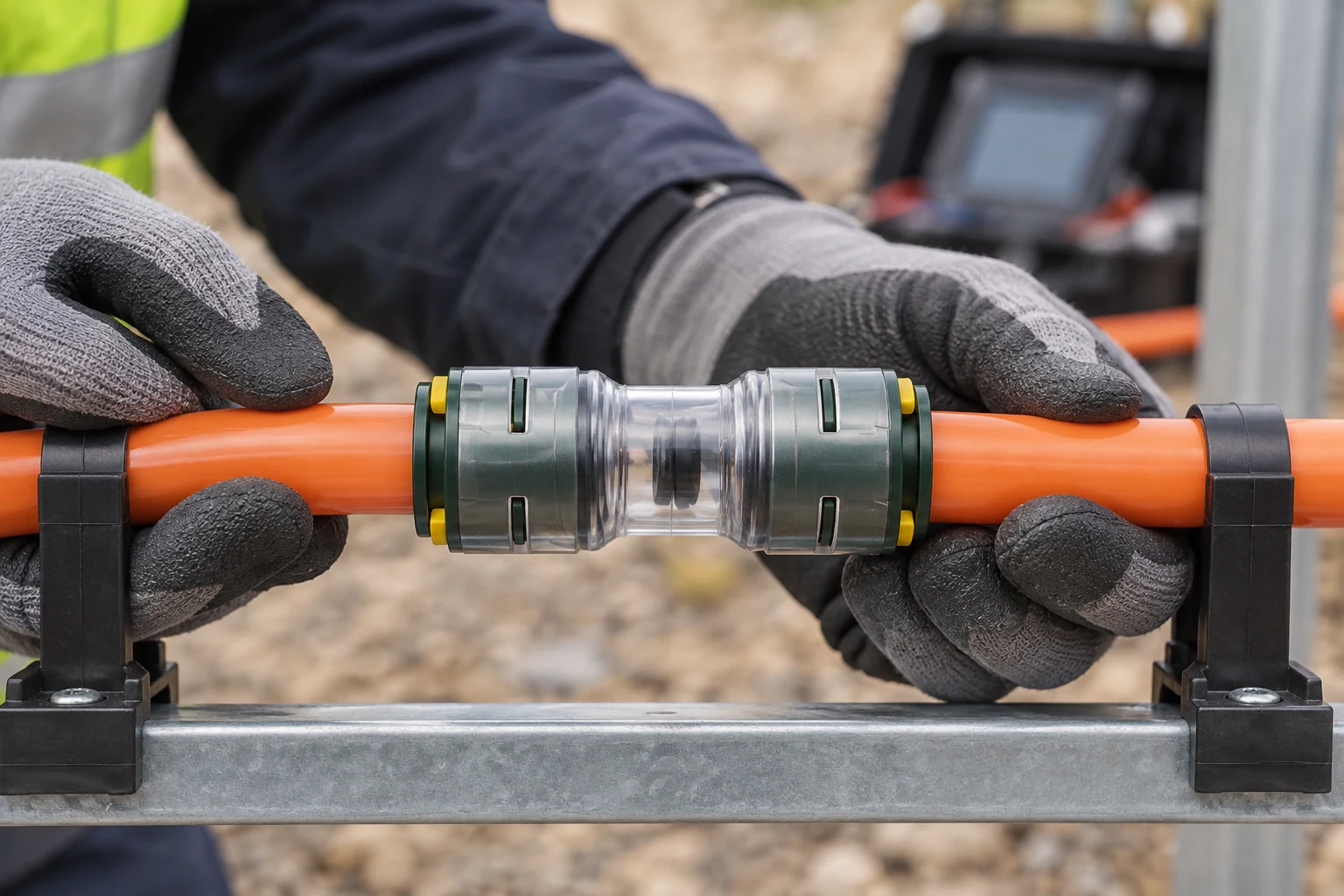
EN 50411-2-8 is a product specification for sealed air-blown-fibre microduct connectors, Type 1, and a basis for discussing performance evidence. Citing it in marketing is not the same as supplying a certificate or test report for the purchased part.
IEC 60794-5-20:2014 addresses outdoor microduct fibre units, microducts, and protected microducts intended for installation by blowing. ITU-T L.79 addresses optical-fibre cable elements for microduct blowing installation. These references help define the system context; neither should be presented as proof that a particular FTTH telecom connector has a certain pressure rating, service temperature, UV life, or reusable status.
For handover, require the contract’s exact revision and part-number evidence. Pressure, hold time, installation and operating temperature, UV exposure, chemical compatibility, sealing function, and reuse must come from exact-part documentation. Add destination-market, operator, or project requirements to the approved submittal before purchase.
Request These Four Documents Before Ordering
- Freeze the interface: issue a duct schedule showing outside diameter, wall profile, location, and the designated connector end for every transition.
- Approve one revision: retain the exact drawing, installation sheet, and applicable test evidence linked to the ordered part code.
- Coordinate the route: check the selected HDPE mikrokanal, connector, cable, and cable blowing equipment as one system rather than four independent purchases.
- Define acceptance: put the approved test medium, pressure, duration, temperature conditions, leak criterion, and record format in the work pack.
Oulu/ANMASPC can support connector and microduct sourcing, but buyers should still request current documents for the quoted part and route. No brand name or family label replaces that check.
Često postavljana pitanja
Can the Air Blown Fiber Microduct Connector be reused after the duct is disconnected
Only if the exact instructions permit reuse and define release, inspection, duct preparation, and retesting. Removal can affect collets, seals, or bodies without obvious damage. If documentation is silent, treat reuse as unapproved and obtain the supplier’s written disposition.
Which material and UV rating are best for outdoor Air Blown Fiber Microduct Connector applications
There is no universal best material or UV value without the exposure, enclosure, temperature, chemicals, and design life. Request the material declaration plus UV test method, duration, criterion, and use limitation for the ordered part. Do not infer outdoor suitability from colour or a family brochure.
Why does the Air Blown Fiber Microduct Connector leak during or after fiber blowing
Possible causes include the wrong diameter pairing, an angled or crushed cut, contamination, scoring, incomplete insertion, missing retainers, side load, or a test above documented limits. Depressurize, identify the part, and inspect against its instructions. Replace suspect components instead of adding unapproved sealant.
Do you need tools or lubricant to fit the Air Blown Fiber Microduct Connector correctly
A suitable cutter and any part-specific preparation or release tool may be required. Use lubricant at the interface only when the exact instructions specify its product, amount, and location. Cable-blowing lubricant is not automatically compatible with connector seals.
How can the Air Blown Fiber Microduct Connector join ducts with different wall thicknesses
Wall thickness alone does not determine fit; each end must match a permitted outside diameter and geometry. For different outside diameters, use a documented reducer instead of forcing a straight model. For equal outside diameters but different wall profiles, obtain an exact compatibility statement.
What temperature range should the Air Blown Fiber Microduct Connector withstand?
The range is project-specific, and installation temperature may differ from operating or storage temperature. Compare route minima and maxima with the exact-part datasheet and test evidence. Never accept a range copied from another size, seal option, or series.
What to Check Before Approving the Installation
This installation succeeds when both duct ends, the connector function, the insertion position and the test method are identified before the air line is opened. Square cuts, clean sealing zones, strain-free support and a recorded retention check address the field decisions that determine whether the joint can be accepted. Pressure, hold time, temperature, UV exposure and reuse still require exact-part evidence; neither the standards nor a catalogue family supplies those limits automatically. For the wider network context, compare this sequence with the fiber-optic cable connector guide and the FTTH fittings-versus-couplers comparison before freezing the work pack.
Reference
- International Telecommunication Union, ITU-T L.79: Optical fibre cable elements for microduct blowing-installation application, 2008.
- International Electrotechnical Commission, IEC 60794-5-20:2014: Outdoor microduct fibre units, microducts and protected microducts for installation by blowing.
- gabo Systemtechnik, Transparent permanent connectors, manufacturer product guidance.
- gabo Systemtechnik, Blowing fibre optics into speedpipe, installation-system overview.
The installation is ready for approval only when the duct pair, connector function, insertion position, support and test method are all recorded. Clean square ends and an undisturbed seal make the joint inspectable; the exact product documents set the limits for pressure, time, temperature, UV exposure and reuse. In practice, a short documentation check before fibre blowing is easier to manage than diagnosing a leak after the route is closed.


