
When a fiber-construction foreman in Brisbane connected two 12/10 mm ducts beside a street cabinet, he released the section for blowing after a quick pull test. Within minutes, a hissing joint and a stalled cable made the failure visible. The first assumption was that the outdoor coupler had failed in the heat; the inspection found an angled HDPE cut, incomplete insertion and a duct outside the fitting’s stated dimensional range. A correctly specified, cleanly prepared joint restored the route—showing that selection and process, not simply product quality, determine service life.
The short answer is: An outdoor microduct coupler should be selected to the measured duct outside diameter (OD), wall construction, exposure conditions and documented test limits; then it should be fully seated and pressure-tested before fiber blowing. IEC 60794-5-20 addresses outdoor microduct systems for blown optical-fibre cables, while IEC 61300-2-34 is an air-pressure resistance test method, not a blanket approval for every fitting. Specify the complete assembly, record its test conditions and replace damaged sealing parts rather than chasing leaks after cable installation.
What gives an outdoor microduct coupler a reliable service life?
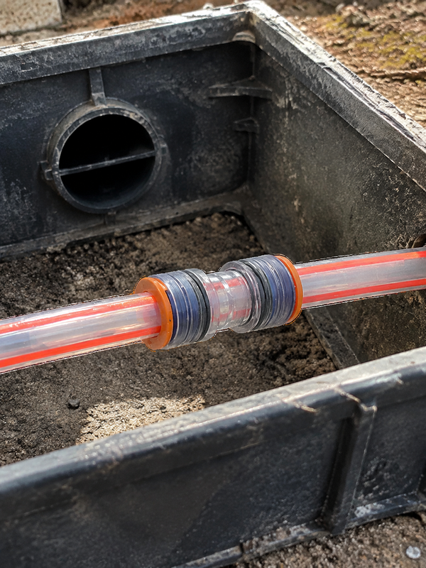
A straight coupler joins compatible ducts in-line while preserving an air path for blown fiber. A transparent body can show seating, but it does not prove that the OD, wall thickness or seal compound is appropriate.
For outdoor work, start with the duct manufacturer’s data and the connector data sheet. Check duct OD, ID, wall thickness, ovality, resin type, temperatures, UV exposure, chamber chemicals, and whether the joint is buried, enclosed or exposed. ASTM D3350 classifies polyethylene compounds; it helps define material language for PE duct, but it does not qualify a particular connector-and-duct joint.
Sunlight, high surface temperature and repeated expansion can stress a fitting at a riser, cabinet entry or exposed handhole. Ask the supplier which weathering or UV test applies to the exact body material, duration, specimen condition and pass criterion. ISO 4892-2 is a laboratory xenon-arc exposure method, not a universal outdoor-service certification. Request separate minimum installation and maximum operating temperatures, because a duct, body and O-ring may have different limits.
Prepare HDPE duct and install the joint without hidden damage
A tool-free push-fit coupler is fast only when the duct end is ready. Cut each HDPE duct squarely with a suitable cutter; remove loose burrs, swarf, mud and moisture; then examine the bore for crushing or deep scoring. Side cutters and a hurried hand cut can leave an angled face that displaces an O-ring or creates a restriction for the blowing head.
- Read the duct marking and measure the actual OD at more than one orientation if the end appears oval.
- Confirm that both ducts are within the fitting’s approved OD, wall-thickness and material range; use a reducer when sizes differ.
- Mark the manufacturer’s insertion depth on each duct, then push straight to the positive stop without twisting the body.
- Where the body is transparent or includes a witness window, confirm that the duct end has passed the seal and reached the indicated seat.
- Give the duct a controlled, light pull only as permitted by the installation instruction; support the route so bending load is not carried by the coupler.
Transparent body inspection is especially useful in poor-access locations: clean the exterior first, use adequate light and look for the duct end at the stated visual reference on both sides. A visible end short of the reference means stop and rebuild the joint. A seemingly correct view is still only one control; it must be followed by the agreed pressure-hold test. For more field process detail, see the site’s guide to installing and maintaining HDPE microduct.
Test for air loss before fiber blowing, not after a cable stalls
Air loss reduces the pressure differential and flow available to move a cable, so a poor joint can look like a cable or compressor problem. Isolate the completed duct section, use clean dry air and the project’s approved closures, then test at the lower of the system’s stated test pressure and the connector’s documented limit. Record start and finish pressure, stabilization time, ambient temperature, test length and acceptance criterion. Never import a pressure or hold-time number from another connector family.
IEC 61300-2-34 describes resistance to air pressure for fibre-optic interconnecting devices and passive components. It is useful for understanding how a declared air-pressure test should be identified, including its configuration; it does not replace the network owner’s acceptance procedure. ISO 1167 covers determination of resistance to internal pressure for thermoplastics pipes, fittings and assemblies, a qualification test that should not be confused with a short field leak check.
During fault-finding, do not compensate by increasing blowing pressure. First divide the route into testable sections, inspect every suspect transparent body and use an approved external leak-detection technique. Fix the cut, insertion or component issue, then retest before fiber installation. This approach avoids wasting a blowing window and helps protect the cable jacket from an unexpected bore step. The related air-blown optical-cable installation overview helps place connector testing in the larger construction sequence.
Value comparison: specialized straight fitting versus an unverified substitute
| Decision factor | Specified microduct coupler | Generic or unverified tube coupler |
|---|---|---|
| Purpose | Like-for-like microduct joint within stated limits | May serve another pneumatic or tubing application |
| Bore continuity | Verified against compatible duct geometry | Must be checked for a lip, restriction or mismatch |
| Outdoor material evidence | Can be requested for the exact SKU and exposure | Often unclear until documentation is reviewed |
| Fiber-blowing risk | Lower when installed and tested to the method statement | Higher verification burden before route release |
| Maintenance tendency | Defined seal, reuse and replacement guidance | Unknown seal compatibility or spare-part path |
| Total-cost effect | Supports predictable acceptance and handover | May create rework, diagnostics and missed blowing slots |
Dimension and environment matrix for procurement
| Project dimension | What to confirm | Evidence or action |
|---|---|---|
| Duct geometry | OD, ID, wall thickness and ovality on both ends | Duct data sheet plus sample measurements |
| Joint type | Straight, reducer, repair or gas-block requirement | Part drawing and compatible size range |
| Outdoor exposure | UV, temperature, moisture, burial depth and chemicals | Material declaration and applicable environmental-test evidence |
| Blowing duty | Route pressure, cable type and acceptance process | Project method statement and pressure-test record |
| Lifecycle plan | Inspection interval, permitted reuse and spares | Supplier installation and maintenance instructions |
Nominal markings illustrate why wall thickness matters. A 12/10 mm duct has a nominal 12 mm OD and 10 mm ID, giving a calculated 1 mm wall; a 14/10 mm duct has a 2 mm nominal wall. Those calculations do not establish tolerances or compatibility. If OD changes, specify a microduct reducer connector; if OD is nominally equal but wall construction differs, obtain written confirmation for the exact duct and fitting combination.
Standards, claims and service maintenance
IEC 60794-5-20 provides a relevant system context for outdoor microducts used with blown optical-fibre cables. IEC 61300-2-34, ISO 1167 and ISO 4892-2 are test methods or test standards with defined scopes; none automatically certifies every product sold into every market. National utility rules, client specifications, environmental conditions and the final product documentation determine what evidence is needed.
Unsupported phrases such as “maintenance-free,” “leak-proof” or “UV-proof” can cause submittal disputes because they omit configuration, duration and conditions. Require a part number, material information, applicable test report, batch traceability and approved installation procedure. Replace the body or seals when the supplier’s inspection criteria call for it, or immediately after a crack, persistent pressure decay, damaged collet, visibly displaced O-ring, chemical attack or an unauthorized removal event. Store spare seals cleanly and away from heat and sunlight; do not fit a replacement O-ring of unknown compound.
Five checks before you order an outdoor microduct coupler
- Freeze the actual duct schedule first—OD, wall, resin, reel batch and location—not just the nominal name.
- Match a micro straight coupler only to the supplier’s stated range; use a reducer for a true diameter transition.
- Define the outdoor exposure and installation temperature in the purchase specification.
- Require a representative installation, visual seating check and recorded pressure-hold test before batch acceptance.
- Order approved spares and document whether the Microduct Coupler-Straight Connectors may be reused after release.
Microduct Connector can help buyers align a Microduct straight fitting with duct dimensions, outdoor conditions and documentation needs. Review the available connector options alongside the project’s test criteria rather than selecting by appearance alone.
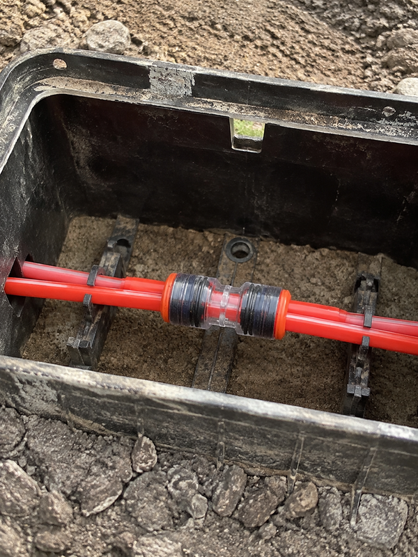
Which outdoor evidence belongs in a coupler approval package?
Outdoor service life is not established by the word outdoor on a product label. The approval package should identify the material, seal type, UV and temperature exposure assumptions, installation position, drainage or water-risk context, inspection access and the test evidence for the exact design. A route owner can then decide whether the connector is suitable for a cabinet, handhole or buried transition.
Cross-check the microduct connector catalogue with the reducer option and the technical contact page when the route includes different duct sizes or unusual exposure.
Frequently asked questions
How can the microduct coupler join ducts with different wall thicknesses?
Equal OD does not automatically mean equal compatibility. Confirm the duct material and wall-thickness range approved for the fitting; where OD differs, use a purpose-designed reducer rather than forcing a straight coupler onto either duct.
What temperature range should the microduct coupler withstand?
The required range comes from the site, including installation conditions, enclosure heat, solar exposure and the lowest seasonal temperature. Request separate operating and installation limits for the exact body and seal, then compare them with the project specification instead of relying on a generic plastics range.
How can installers visually check that the microduct coupler is fully seated?
Mark the stated insertion depth and confirm that the mark reaches the body reference; on a transparent body, verify that the duct end has passed the seal and reached the internal stop. This check supports, but cannot replace, a pressure test because a damaged or incompatible duct can still look seated.
When should the seals or body of the microduct coupler be replaced?
Replace the affected part after a crack, seal nick, chemical damage, damaged collet, unexplained air loss or a removal event that the manufacturer does not permit for reuse. Use only approved replacement parts and repeat the joint test after maintenance.
Where can installers use the microduct coupler in fiber and telecom networks?
Installers use compatible in-line couplers in access routes, FTTx distribution sections, handholes, cabinets, building entries and repair locations. The selected body, seal and protection method must suit whether the joint is indoors, buried, enclosed or exposed outdoors.
How do you choose the correct duct diameter for the microduct coupler?
Measure OD, ID, wall thickness and ovality, then match the actual OD to the connector’s published range. Verify both ducts independently and retain the measurement record with the order, especially when ducts come from different reels or manufacturers.
Does an outdoor rating prove a connector will last for the whole network design life?
No. Service life depends on the exact material, seals, UV and temperature exposure, mechanical support, water conditions and maintenance plan. Request the applicable test scope and installation limits for the selected model.
Should an outdoor coupler be pressure-tested before or after burial?
Test the accessible assembled section before it is covered, using the project acceptance method. Repeat checks after any disturbance or repair and keep the result with the as-built route record.
References
- IEC 60794-5-20: Microduct cabling for installation by blowingOfficial IEC Webstore page; outdoor microduct-system context.
- ITU-T L.1700: Requirements for outside plant optical fibre cable networksOfficial ITU recommendation page; outside-plant planning reference.
- ASTM G154: Operating fluorescent ultraviolet exposure apparatusOfficial ASTM page; UV-exposure test-method context, not a product guarantee.
A dependable joint is specified, seated and proven before it is hidden by the next stage of construction. When your team is ready to compare dimensions and evidence for a microduct coupler, contact Microduct Connector with the duct schedule, route environment and test requirements.


