
When a fiber-installation supervisor in Manchester encountered a falling air-pressure reading during a last-mile blow, she first blamed the compressor. The crew isolated the handhole and measured both HDPE ducts; a nominally similar straight fitting crossed two different outside diameters. A correctly sized reducer stopped the leak, showing the root cause was selection and installation control, not simply a bad fitting.
The short answer is: A Microduct Reducer Connector must be selected from measured duct OD, ID, wall thickness, and blowing route—not a nominal label. Make two checks at each side, inspect the seal, and confirm the fitting data with the supplier. IEC 60794-5 is relevant outdoor-cable context, not an automatic connector certification. Record both duct measurements before ordering and perform a controlled installation check before the blowing crew mobilizes.
Reducer fittings join different duct sizes while preserving a practical pneumatic path for cable installation. The right choice protects schedule and cable handling; the wrong one can create an air-loss point that resembles a compressor or cable problem.
Start with actual microduct dimensions, not the label
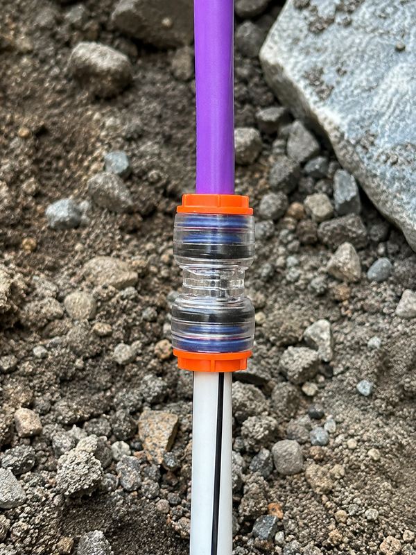
A Microduct reducer has two connection ends, and each end must match the duct it receives. Procurement should obtain the duct manufacturer’s declared OD and ID, then have the installer measure the actual exposed ducts with a suitable caliper. Take two readings per duct—one close to the intended cut and one slightly back from it—because an oval, damaged, or poorly cut end can prevent a seal from seating evenly.
Why wall thickness changes the decision
Two ducts can share a similar OD yet have different wall thicknesses, which changes ID and therefore the air path and cable clearance. The reducer’s retaining and sealing geometry normally works at the outside of the duct, while the blowing result also depends on the internal transition. Ask for confirmation that the proposed end size accepts the measured OD and that the resulting ID transition is suitable for the cable and blowing method. IEC 60794-5 provides a useful standards reference when the route includes outdoor microduct cable; use the applicable published scope and project specification rather than assuming a generic duct relationship.
Make the cut part of the specification
Cut the duct squarely, remove loose burrs, and keep the end round and clean. A reducer cannot compensate reliably for a crushed section, deep scoring, or an oblique cut that leaves one side short of the seal. For a distributor, this is a low-cost inspection step; for a contractor, it prevents a high-cost return visit after reinstatement. Record the two duct sizes, duct material, cable type, and route location on the installation pack.
Protect fiber-blowing performance by diagnosing the whole air path
In a pneumatic installation, the connector is one part of a sealed system: compressor, blowing equipment, cable, duct, fittings, and any branches all influence the result. A leak at a reducer may show as unstable pressure or reduced cable progress, but those symptoms do not identify the cause by themselves. Treat troubleshooting as a section-isolation exercise, not a reason to tighten or replace fittings at random.
Before blowing, visually check that each duct reaches the insertion depth required by the fitting design, that the collet has not been damaged, and that the O-ring or other seal is clean, present, and free of nicks. Then follow the project’s controlled pressure-check procedure and the equipment supplier’s instructions. Where the route needs to stop gas migration as well as join ducts, assess whether a dedicated microduct gas block is required; a reducer should not be assumed to perform every sealing function in the network.
Named test methods and standards are useful only when their scope matches the item being specified. For example, EN 50411-2-8 should be checked in its current published form for the relevant fibre-management context; it does not, by its title alone, prove an individual reducer’s pneumatic performance. Require the supplier’s applicable data, installation instructions, and any project-required test evidence before releasing material to site.
Choose straight or reducer fittings by the transition you really have
A straight connector is a sensible choice only where both ducts meet the fitting’s matching-size requirement. A reducer is for a deliberate size transition. Substituting one for the other because parts are available locally can create a hidden compatibility risk, especially when nominal sizes, SDR-style wall relationships, or supplier conventions differ.
| Decision factor | Straight connector | Reducer connector |
|---|---|---|
| Performance intent | Maintains a same-size duct run when both ends match. | Manages a planned change between verified duct sizes. |
| Compatibility | Requires matching specified OD at both ports. | Requires the specified OD range at each different port. |
| Installation | Simple push-fit after square, clean cuts. | Also tool-free push-fit, but the two ends must not be reversed. |
| Maintenance | Inspect both seals after disconnection or route work. | Inspect both seals and recheck the transition after any rework. |
| Total cost of ownership | Lower complexity where no transition exists. | Can avoid adapters, leak diagnosis, and rework when a transition is real. |
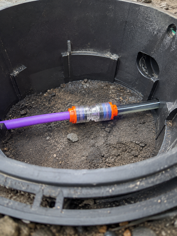
For same-size repairs or extensions, compare the required dimensions with a straight microduct connector. For mixed-diameter routes, document the reducer orientation on the plan and label the two duct sizes at the handhole. That small discipline makes later fault isolation faster and gives procurement an auditable basis for substitutions.
Plan for outdoor exposure and seal maintenance
Outdoor telecom infrastructure exposes fittings to sunlight, temperature cycling, moisture, and soil contamination. Select material from the supplier’s stated UV and temperature performance for the site. Do not infer a UV or temperature rating from colour or transparency.
Keep O-rings and seals clean, avoid sharp tools and incompatible chemicals, and replace visibly damaged components with approved spares. Lubricant is not a substitute for a clean, square cut; use it only when product instructions say so. The EU RoHS framework may matter when a product falls within its electrical-and-electronic-equipment scope, so check applicability rather than presume it.
| Application | Duct OD relation | Selection check | Air-blowing consideration |
|---|---|---|---|
| FTTx branch into a smaller distribution duct | Upstream OD differs from downstream OD. | Measure both ODs and confirm each reducer port. | Confirm cable and ID transition with the blowing plan. |
| Handhole repair after a duct replacement | Existing and replacement ducts may use different wall thicknesses. | Verify OD, ID, material, and end condition—not the label only. | Isolate the repaired section before resuming the blow. |
| Outdoor feeder transition | Different duct families or suppliers may meet. | Check stated UV and temperature suitability for the exact fitting. | Protect seals from grit and inspect after chamber work. |
| Same-size route extension | Both measured ODs match the same fitting end. | Select a straight fitting rather than creating an unnecessary reduction. | Check all nearby joints if the route loses air. |
Standards, regulatory scope, and procurement evidence
Standards can guide specification, but they do not automatically certify a product. IEC 60794-5 concerns outdoor microduct optical-fibre cables; read its current scope and test references for the cable-system design. EN 50411-2-8 should likewise be checked against the actual interface being specified. Neither reference alone shows that a particular Micro Duct Reducing Connector has passed an air-tightness or environmental test.
ETSI’s standards catalogue helps identify telecommunications requirements that may apply to a customer specification. The EU RoHS Directive restricts certain substances in electrical and electronic equipment; a passive duct fitting is not automatically in scope. Unsupported claims create tender and traceability risk, so request relevant declarations, test reports, or material statements where the market and project require them.
A practical procurement checklist for a Microduct Reducer Connector
- Measure and record the OD and ID of both ducts; photograph damaged or oval ends before cutting them back.
- Confirm each reducer-port size, permitted duct material, and installation instructions with the supplier.
- Match the internal transition to the cable, blowing equipment, and route design; treat any calculation as route-specific.
- Specify outdoor UV and temperature evidence for the exact fitting where the route environment requires it.
- Keep a small, approved seal-spares plan and define the pressure-check process before field installation.
Oulu, Zhejiang Oulu Automatic Equipment Co., Ltd., supplies microduct connectors, HDPE microduct systems, cable-blowing accessories, and pneumatic fittings, with configurable selection support. Buyers can review the broader micro duct reducer and connector range alongside measured dimensions and documentation needs.
What does a buyer need before ordering a reducer connector?
Three pieces of evidence should precede the order: measured dimensions for both ducts, the route and environment, and the supplier’s installation and test limits. OD identifies the interface, while ID and wall thickness help confirm the usable bore and mechanical condition. A nominal label alone cannot prove that a reducer will seal or preserve the air path.
Use the straight connector page to test whether a transition is really needed, then compare the reducer range and gas-block option when the route also needs temporary protection or sealing.
Frequently asked questions
Can the Microduct Reducer Connector be reused after the duct is disconnected?
Possibly, but only if the fitting design permits it and the body, collet, and seal pass inspection. Cut back any deformed duct end, clean the components, and replace damaged approved seals before reuse. For critical routes, follow the supplier’s reuse guidance and repeat the project’s controlled check.
Which material and UV rating are best for outdoor Microduct Reducer Connector applications?
The suitable material and UV rating depend on the exact fitting, exposure, temperature cycle, and destination-market requirements. Ask for the manufacturer’s documentation for the specified item rather than relying on a generic polymer description. In a protected handhole, contamination and handling may matter as much as direct sunlight.
Why does the Microduct Reducer Connector leak during or after fiber blowing?
Common causes include a wrong measured OD, an unsquare or scored duct end, incomplete insertion, contamination, or a damaged seal. Isolate the route section and inspect it methodically; a pressure symptom by itself does not prove the reducer is at fault. Also check adjacent joints and any component added during the same work.
Do you need tools or lubricant to fit the Microduct Reducer Connector correctly?
Push-fit reducers are intended for tool-free connection, but the duct still needs a clean, square cut and correct insertion. Do not add lubricant by default, because it may attract contamination or be incompatible with the fitting. Use any preparation tool or lubricant only where the product instructions specifically call for it.
How can the Microduct Reducer Connector join ducts with different wall thicknesses?
Wall thickness affects ID even when the duct ODs look similar. Select each reducer end by the measured OD it must seal, then verify that the resulting internal transition suits the cable and blowing plan. If the duct family or material is uncertain, obtain compatibility confirmation before installation.
What temperature range should the Microduct Reducer Connector withstand?
There is no responsible universal temperature figure for every reducer. Specify the actual minimum and maximum service conditions for the route, then obtain the fitting’s documented temperature suitability from the supplier. Include installation-time conditions as well as the expected outdoor service environment.
Is the duct ID more important than OD when choosing a reducer connector?
Both matter, but they answer different questions. OD controls the fitting interface; ID and wall thickness help assess bore continuity and duct condition. Confirm all dimensions against the selected model’s range and installation drawing.
Can a reducer fix an air leak caused by an oval or damaged duct end?
No. A reducer cannot compensate for a damaged sealing land. Cut back to sound material, make a square cut, clean the end, verify insertion and then select the reducer for the measured interfaces.
References and the next decision
- IEC Webstore: IEC 60794-5 microduct systemsOfficial IEC search page; microduct-system context.
- ITU-T L.1700: Requirements for outside plant optical fibre cable networksOfficial ITU page; outside-plant planning reference.
- ASTM D3350: Polyethylene plastics pipe and fittings materialsOfficial ASTM page; PE material reference.
Measure the duct, respect the seal, and let the transition—not the part label—drive the choice.
When a size transition is real, review Oulu’s Microduct Reducer Connector options against your measured duct data, then contact the team for configurable product or project-selection support.


