When a fiber crew leader in Rotterdam prepared an underground-to-building route, he tightened the water-block seal before the cable arrived. The next blowing attempt stopped quickly and left a visible jacket mark. Loosening the seal restored the path: the fitting was not inherently faulty, but its activation step had been placed on the wrong side of cable installation.
Summary: Activate a Water Block Microduct Connector after cable placement unless the manufacturer’s verified procedure explicitly requires another sequence. Select it using measured duct OD and the cable’s full diameter tolerance, then test the assembled joint. The referenced product family lists 0.8 MPa air tightness, 2.5 MPa proof pressure, and an operating range to 1.6 MPa (16 bar); confirm these values for the exact code rather than applying them to all water-block connectors.
Set the seal activation point before cable work begins
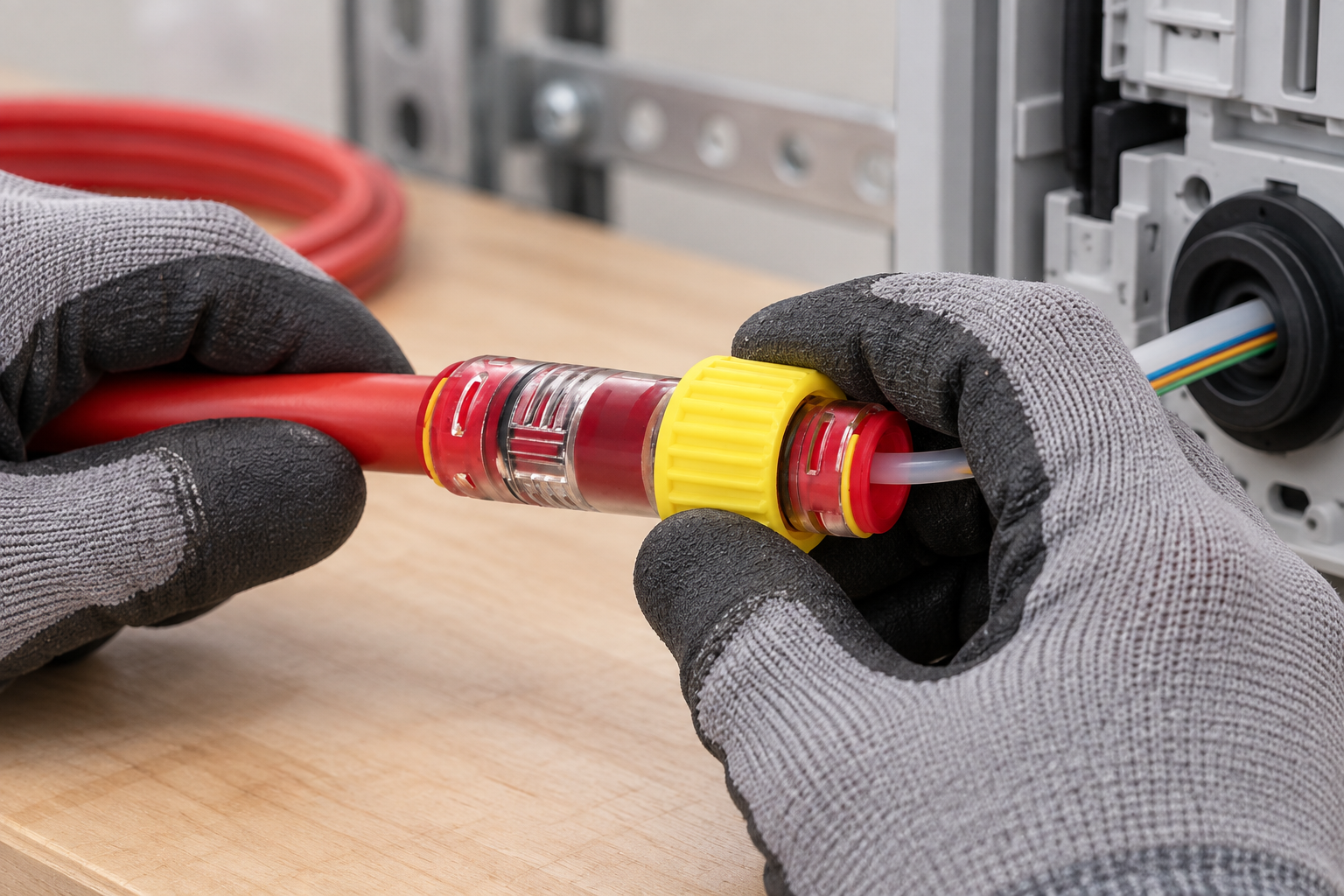
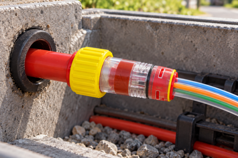
The water-block element occupies the annular space between cable and microduct. Before the cable passes, that space must remain open enough for the approved blowing process. After the cable reaches its position, the seal can be compressed or activated according to its design. Treating activation as an undocumented installer preference creates inconsistent friction, cable damage, and leakage.
A controlled method uses hold points: verify the connector is the correct way round; prepare and seat the duct; confirm the seal is relaxed; blow or pull the cable within the system limit; inspect the jacket; activate the seal; then test. A Gas And Water Block Microduct Connector can address migration at the cable annulus, but it does not automatically seal the wall penetration or replace an approved building-entry system.
Make the decision from route state, not from the calendar. If the cable must still travel, remain accessible for proving, or be replaced during the same work window, keep the seal in the documented open state. Activate only when the cable is at final position, its jacket passes inspection, the connector is supported, and no further movement is planned. Record who released that hold point; this prevents a later crew from assuming that a visually complete fitting is already sealed.
Verify duct OD and cable range as two independent fit decisions
Two nominal numbers govern the choice. The first is duct OD, which determines grip and the outer sealing interface. The second is cable diameter, including production tolerance and any local ovality, which determines annular-seal compression. Duct ID and wall thickness also affect bore continuity and available clearance. A product described only as “14 mm” is therefore incomplete for purchasing.
Measure a clean duct sample in two axes and obtain the cable maker’s minimum and maximum jacket OD. Confirm that both fall inside the precise connector code’s range. The site’s push-fit size and pressure comparison gives useful context, but the purchase schedule should cite an exact drawing rather than a product-family label.
| Seal state | Cable operation | Benefit | Primary risk | Decision rule |
|---|---|---|---|---|
| Relaxed/open | Before and during blowing | Preserves cable path | Migration not yet controlled | Use until cable reaches final position |
| Partly engaged | Only if instructions define it | May stabilize a specific design | Unmeasured drag or jacket marking | Never improvise an intermediate setting |
| Fully activated | After placement | Seals cable annulus | Over-compression or wrong cable range | Activate to stated torque, travel, or stop |
| Released for service | Maintenance or cable change | Restores access | Reusing damaged seals | Depressurize and follow the reopening procedure |
Use the transparent body to inspect seating, then prove each leakage claim separately
A transparent body can show whether the tube has reached the insertion position, whether a seal is displaced, and whether dirt or moisture is trapped inside. Add an insertion-depth mark before assembly so the view has a reference. Optical clarity may decline outdoors, so specify polymer and UV evidence appropriate to exposure; ISO 4892-3 defines fluorescent-UV conditioning but is a test method, not a service-life certificate.
Visual inspection cannot reveal a microscopic leak or confirm the holding capability of the complete route. Pressure testing should use the lowest safe limit among duct, connector, cable seal, end closure, gauge, and test hose. Increase pressure gradually, allow temperature stabilization, hold for the specified period, check interfaces, and document loss limits. The exact product page’s 1.6 MPa maximum equates to 16 bar, so a 16 bar requirement is a product-data verification checkpoint—not a generic rating.
For a liquid-ingress claim, define the water exposure, head or pressure, duration, orientation, and acceptance condition. For air or gas, define medium, pressure, hold time, permitted decay, temperature correction, and leak-location method. IEC 60529 can support an ingress-protection claim for a tested configuration, but it does not replace the route-specific cable-annulus test.
Do not treat “no visible water” and “gas tight” as interchangeable outcomes. A narrow path can resist liquid water under one head yet pass a detectable quantity of air or gas, and elastomer response can change with medium and temperature. If both duties matter, write two acceptance cases or use a validated combined procedure. Record the exact duct, cable, seal state, medium, stabilization time, temperatures, hold time, and initial and final readings so the result can be compared after maintenance.
| Checkpoint | Question | Pass evidence | Action if failed |
|---|---|---|---|
| Duct interface | Is OD correct and tube fully seated? | Measurement plus visible insertion mark | Depressurize, remove, recut, and reseat |
| Cable interface | Is jacket within the stated sealing range? | Cable data and sample measurement | Select the correct seal/code |
| Activation | Was the maker’s torque/travel reached? | Recorded setting or positive stop | Correct only after inspection |
| Pressure | Did the assembly meet the agreed hold test? | Calibrated-gauge record with temperature | Locate leak; do not simply over-tighten |
| Water pathway | Is the wall penetration also sealed? | Approved entry detail and inspection | Add the specified penetration system |
| Maintainability | Can the joint be safely reached and reopened? | Access clearance and spare-seal plan | Redesign location or protection |
Depressurize and inspect every sealing surface before reopening the connection
First isolate and depressurize the route, confirm zero stored pressure, clean the exterior, remove any locking feature, and release the seal using the maker’s sequence. Support the cable and duct so that twisting the body does not transfer load into the jacket. Never lever against a transparent body or pull the duct while the collet remains engaged.
After opening, inspect the O-ring and cable seal for cuts, flattening, swelling, hardening, embedded grit, and chemical attack. Inspect the cable jacket for grooves and the body for crazing or distortion. Replace single-use or damaged sealing parts; do not assume that a previously compressed elastomer will recover. The related microduct closure troubleshooting guide covers retention and preparation faults that can also appear during reassembly.
After reassembly, treat the connector as a new acceptance point: restore the insertion reference, confirm the cable is centered and unstressed, activate to the specified endpoint, and repeat the complete leakage test. A quick check at the previously leaking interface can miss damage introduced at the other seal during opening.
Assign connector, wall-entry, fire, and gas-safety duties separately
- IEC 60529: IP-code test framework for enclosures; applicability depends on the tested assembly and condition.
- ISO 4892-3: artificial UV exposure of plastics using fluorescent lamps; results need cycle, time, and property-retention criteria.
- ITU-T L.79: microduct-blowing cable elements, useful for coordinating connector and cable process requirements.
- ITU-T L.87: optical fibre cables for drop applications, relevant where the entry serves access drops.
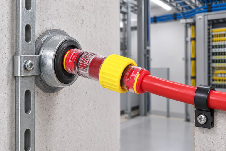
At a building entry, separate five questions: duct support, duct-to-connector sealing, cable-annulus sealing, wall-penetration sealing, and any fire or hazardous-gas requirement. A Water Block Connector For Micro Duct End may answer only some of them. Unsupported claims expose the contractor to rejected inspections and costly rework, so record the exact product, standards scope, test report, and installed configuration.
Purchase and approve the connector against the final installed state
- Specify measured duct OD/ID and cable minimum/maximum OD, not nominal size alone.
- Define whether the fitting closes an empty duct, seals around an installed cable, joins ducts, or combines functions.
- State blowing pressure separately from post-installation working and proof-test requirements.
- Require a visible insertion method, activation instruction, reopening procedure, and spare-seal availability.
- Approve a test plan covering air or gas, water exposure where required, temperature, duration, and acceptance.
Zhejiang Oulu offers configurable microduct gas-and-water block products. Buyers can use its published ranges as a starting point, then require written confirmation that the ordered code matches their duct, cable, environment, test method, and destination-market obligations.
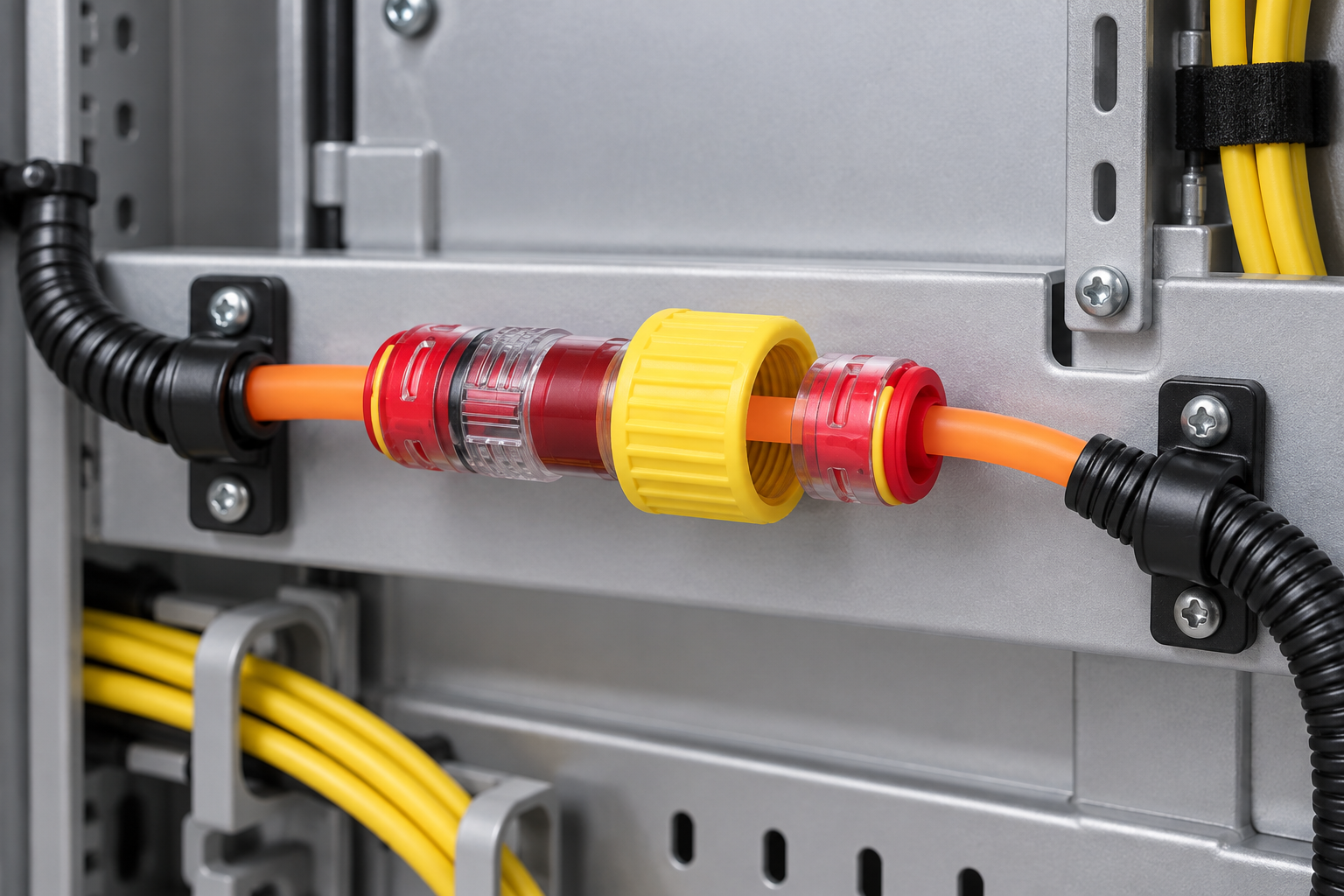
Questions crews ask before activating a water-block seal
What outdoor temperature and UV conditions should the Water Block Microduct Connector handle?
It should cover the project’s installation and operating extremes and the actual sunlight exposure. Verify the exact product’s temperature limits and defined UV conditioning rather than accepting an unqualified “outdoor” label.
How often should a gas-water block connector be inspected?
Inspect it at commissioning, after cable maintenance, after flooding or ground movement, and on a documented risk-based interval. Increase frequency at critical building entries or exposed chambers.
What contaminants does the Water Block Microduct Connector block in a microduct?
A correctly selected assembly can restrict water, humid air, and particles along its designed interfaces. Specific gases or chemicals require separate compatibility and permeation evidence.
Should the gas or water seal be activated before fiber installation?
Normally it should remain relaxed until the fiber cable has been installed, then be activated and tested. Follow the exact instructions because some designs use different preassembly states.
How do you install a Water Block Microduct Connector at a building entry point?
Support the duct, cut and clean it square, seat the correct connector, install the cable, activate the cable seal, and test. Complete the wall penetration with the separately approved entry or fire-sealing system.
What pressure rating is suitable for a Water Block Microduct Connector in an outside-plant network?
The suitable rating exceeds the defined installation and service pressures with the project’s required margin while remaining compatible with every route component. Confirm working, proof, and burst terminology and test conditions for the exact part.
Use these sources to verify the activation and acceptance plan
- IEC 60529, Degrees of protection provided by enclosures (IP Code)
- ISO 4892-3, Plastics—Methods of exposure to laboratory light sources
- ITU-T L.79, Optical fibre cable elements for microduct blowing installation
- ITU-T L.87, Optical fibre cables for drop applications
The correct activation moment preserves the cable path first and closes the migration path second.
Review the published configuration data on the Micro Water & Gas Block Connector And Endcap product page, then contact Oulu with measured duct and cable dimensions, route pressure, entry detail, and reopening requirements.