When a telecom foreman in Manchester joined a 12/10 mm duct at a roadside cabinet before a fiber-blowing shift, the compressor pressure dropped and the cable stopped well short of the next access point. The coupler looked intact; the rapid failure came from a 10 mm duct pushed into one side of a 12 mm straight fitting, plus a rough cut hidden inside the body. Once the crew measured both outside diameters, re-cut the HDPE square, and selected a reducer, the test held. The root cause was specification and preparation—not simply a bad connector.
Summary: A Coupler for HDPE microduct connector should be selected first by the actual duct outside diameter (OD), then by compatible wall range, material, route environment, and the supplier’s stated pressure-test conditions. For example, 12/10 mm normally means a 12 mm OD and about 10 mm ID; it does not establish a universal 12 mm fitting pressure rating. Use a same-size straight coupler for two compatible ODs and a purpose-made reducer for different ODs, then prove the completed section with the project’s documented air test. IEC 60794-5-20 addresses outdoor microduct systems for blown optical fibre cables, so system evidence is more useful than a generic “high-pressure” label.
What a coupler must do in an air-blown fibre route
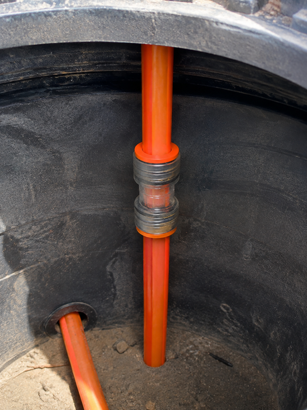
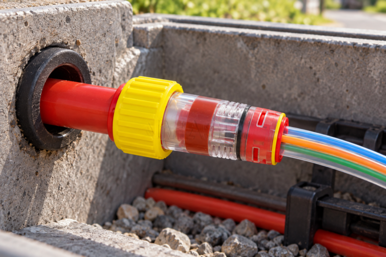
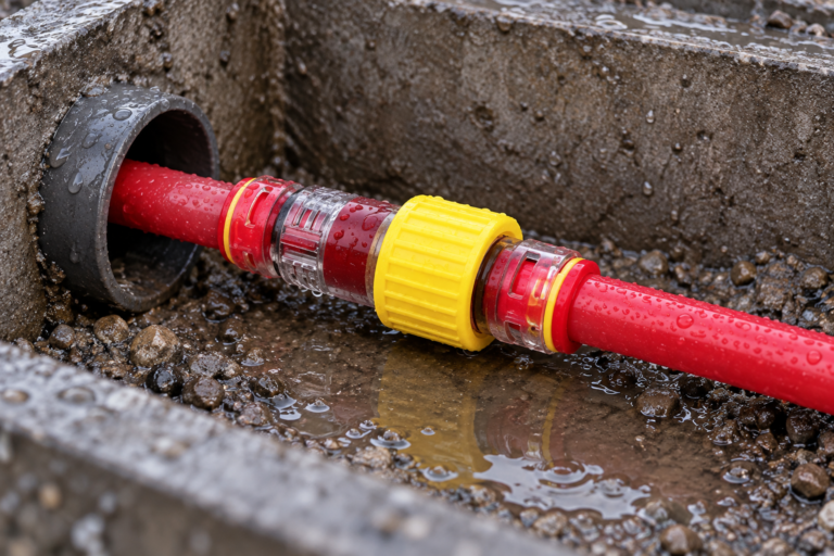
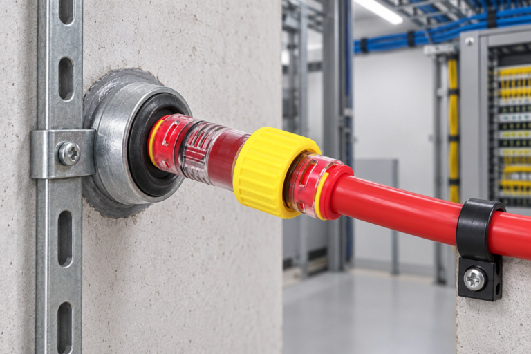
A microduct coupler is an in-line joint intended to keep the duct route continuous while air carries a cable through it. In a push-fit design, a gripping element retains the duct and an elastomer seal helps contain pressure. The fitting must suit the duct’s OD and approved material range; the adjacent ducts must also remain coaxial enough that the joint does not create an avoidable bore step or air-loss path.
Terminology can complicate purchasing. A Straight coupler ftth microduct has the same connection size at both ends; Micro Couplers may also include reducers, end stops, or fittings for other pneumatic tubing. In FTTx and telecom ducts, physical fit is not compatibility—check the data sheet, duct guidance, and owner’s acceptance requirements. See what a microduct connector is for the functional distinction.
Straight versus reducer connector selection
Choose a straight union when both confirmed duct ODs fall within the same connector size and the duct materials and wall ranges are approved. A 12 mm-to-12 mm joint may be appropriate for a 12/10 mm duct pair, subject to the exact product data. Choose a reducer when the route intentionally transitions, such as 12 mm OD to 10 mm OD at a distribution point. Never treat a straight fitting as a reducer by forcing a smaller duct into it; the grip and seal geometry may not engage as designed.
| Decision point | Straight coupler | Reducer connector | Commercial consequence if wrong |
|---|---|---|---|
| Duct OD relationship | Same verified OD at both ends | Two stated, different ODs | Leakage or retention uncertainty |
| Typical use | In-line extension or like-for-like repair | Planned route transition or cabinet interface | Unnecessary rework during commissioning |
| Bore transition | Designed for continuity between matched ducts | Contains a deliberate size transition | Greater blowing resistance if geometry is unsuitable |
| Specification check | OD, wall range, material, pressure conditions | Both ODs, flow direction if stated, pressure conditions | Unclear acceptance responsibility |
| Unit-cost tendency | Usually the simpler geometry | Usually more specialized | Lower purchase cost can be eclipsed by a failed test |
| Total-cost view | Predictable when installed and tested once | Predictable when the transition is documented | Crew time, compressor use, cable delay, and repeat testing |
The total-cost question is not the price of one fitting. An illustrative 30 minutes of two-person fault finding can cost more than correct selection and a recorded installation test. That makes dimensional evidence and system testing part of procurement value. Review the role of microduct fittings in fibre-optic installations for broader context.
Microduct connector size guide: read OD, ID, wall and application together
Order from measured OD, not nominal ID or catalogue shorthand. On a 12/10 mm duct, nominal wall is about (12 − 10) ÷ 2 = 1 mm; this does not replace the fitting’s permitted wall range. Measure at more than one orientation where stored duct may be oval.
| Typical duct marking | Nominal OD × ID | Calculated nominal wall | Common application | Selection question |
|---|---|---|---|---|
| 5/3.5 mm | 5 × 3.5 mm | 0.75 mm | Dense indoor or access microduct bundles | Is 5 mm OD and this wall range approved? |
| 7/5.5 mm | 7 × 5.5 mm | 0.75 mm | FTTx drop or distribution runs | Are both ends the same actual OD? |
| 10/8 mm | 10 × 8 mm | 1.0 mm | Distribution and local access routes | Is this a straight 10-to-10 joint or a transition? |
| 12/10 mm | 12 × 10 mm | 1.0 mm | Feeder and cabinet approaches | Does the fitting state 12 mm OD compatibility? |
| 14/10 mm | 14 × 10 mm | 2.0 mm | Route designs needing a thicker wall | Does the connector accept this wall and material? |
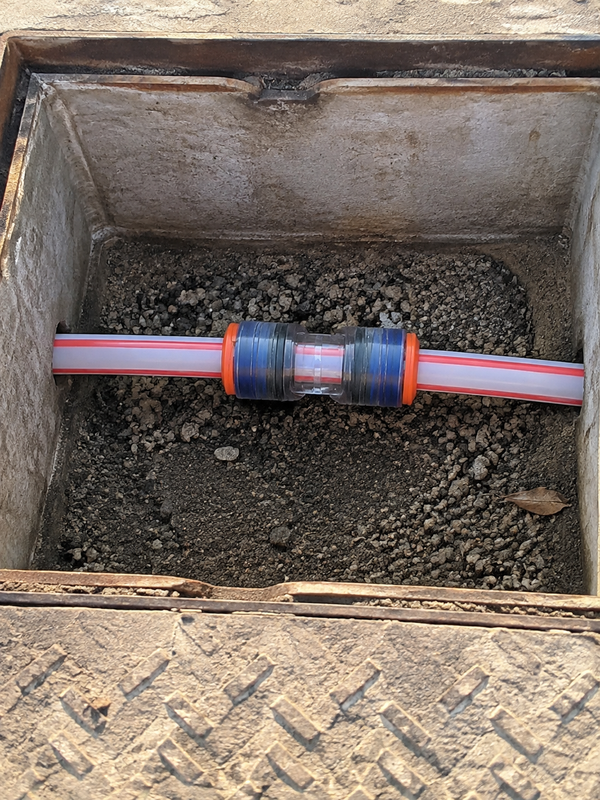
These are common markings, not product specifications. Confirm polymer, wall tolerance, insertion depth, temperature range, and approved bundled-duct use. In a transparent body, check that both clean ends reach their shoulders, remain straight, and show no debris. Appearance is not proof of airtightness.
Pressure ratings, duct preparation and leak-testing steps
A pressure rating belongs to the exact connector-and-duct configuration under stated conditions; it is not created by the duct size printed on the reel. Request the rated operating or test pressure, test medium, temperature, duration, and approved duct range from the supplier. If the route has long sections, many joints, or a high-consequence cabinet location, align the test plan with the client specification before selecting fittings rather than after a blowing failure.
- Identify each duct by manufacturer, OD, ID, wall, and material; reject crushed, split, heavily oval, or heat-damaged ends.
- Cut the HDPE duct square with a suitable cutter, remove burrs without scoring the sealing surface, and wipe away swarf, water, and soil.
- Check the fitting size, seal condition, and insertion-depth mark or stop; insert each duct fully and squarely in accordance with the product instructions.
- Isolate the completed section with approved end closures, use clean dry air, and pressurize only to the project- or manufacturer-specified test value.
- Allow temperature to stabilize, record pressure, time, ambient conditions and test length, then hold for the stated duration and investigate pressure loss under the agreed criterion.
IEC 61300-2-34 is a named test method for resistance to air pressure of fibre-optic interconnecting devices and passive components; it does not automatically certify every microduct coupler. That distinction protects buyers from treating a test-method reference as a blanket product claim. For new outdoor routes, IEC 60794-5-20 provides relevant system context; local street-works rules, utility specifications, and contract documents can impose additional controls.
Standards, materials and outdoor exposure
IEC 60794-5-20 concerns outdoor microduct systems for blown optical fibre cables; IEC 61300-2-34 describes an air-pressure resistance test method. ITU-T L.87 addresses fibre cable-network requirements, while ASTM D3350 classifies polyethylene pipe and fitting materials. No one reference proves a particular Connection for microduct suits a network; applicability depends on market, installation, claims, and product evidence.
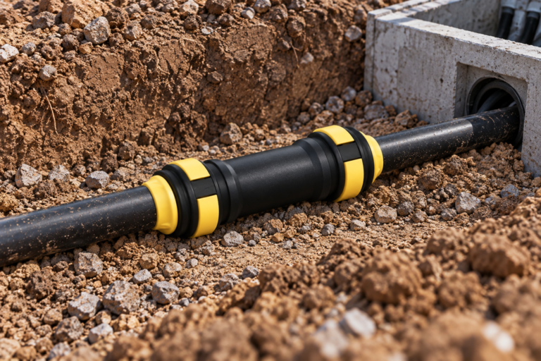
For exposure outdoors, request body and seal material, UV-resistance basis, operating-temperature range, and any enclosure requirement. Black UV-stabilized polymer is common, but colour is not a UV rating. Retain the data sheet and project test record; unsupported claims can create handover and warranty disputes.
A buyer’s checklist before specifying the coupler
- Measure and record both duct ODs; select straight or reducer geometry from those measurements.
- Obtain the compatible material and wall-thickness range, insertion instructions, and tested pressure conditions for the exact part number.
- Check route conditions—burial, enclosure, UV exposure, temperature, and access for future maintenance.
- Define the leak-test acceptance method, pressure, hold time, test-section length, and record format before installation.
- Make transparent-body inspection part of the crew’s sign-off, then complete the pressure test rather than relying on appearance alone.
Microduct Connector can support a documented choice of straight and reducing microduct fittings when buyers provide duct dimensions, application conditions, and acceptance criteria; its guide to choosing microduct fittings is a useful starting point for a sourcing checklist.
FAQ
Where can installers use the Coupler for HDPE microduct connector in fiber and telecom networks?
Installers use it for in-line joins, repairs, cabinet approaches, distribution routes, and other FTTx sections where compatible microducts need a pressure-managed connection. The exact application must match the fitting’s stated duct range and environmental limits; a generic pneumatic coupler is not automatically suitable for an air-blown fibre route.
How do you choose the correct duct diameter for the Coupler for HDPE microduct connector?
Use the measured outside diameter of each duct and match it to the connector’s specified connection size. Confirm wall range, material, and ovality as well; select a straight fitting for equal approved ODs and a reducer for an intentional OD change.
How do you install the Coupler for HDPE microduct connector without causing an air leak?
Make a square, clean, burr-free cut; inspect the seal and push each duct fully to the indicated stop following the manufacturer’s instructions. A transparent body can show seating and debris, but the completed section still needs the agreed pressure/hold test.
What pressure and time should be used to test the Coupler for HDPE microduct connector?
There is no responsible universal pressure or hold time because both depend on the exact connector, duct, temperature, test length, client specification, and test method. Use the supplier’s documented conditions or the network owner’s approved test plan, record the stabilized starting pressure and hold period, and investigate any decay beyond the stated acceptance criterion.
Can the Coupler for HDPE microduct connector be reused after the duct is disconnected?
Only reuse it when the manufacturer expressly permits disconnection and reuse for that model. Inspect the collet, seal, body, and newly cut duct end; if there is any damage, contamination, or uncertainty, replace the fitting and retest rather than risking a hidden leak.
Which material and UV rating are best for outdoor Coupler for HDPE microduct connector applications?
The best choice is the material system with documented UV exposure performance, temperature range, and sealing compatibility for the actual route—not simply a dark-coloured plastic. Request the data sheet and test basis, and use an enclosure or protective installation method where the product documentation calls for one.
References
- IEC 60794-5-20: Optical fibre cables—Outdoor microduct systems for blown optical fibre cables.
- IEC 61300-2-34: Fibre optic interconnecting devices and passive components—Tests—Resistance to air pressure.
- ITU-T L.87: Requirements for optical fibre cable networks.
- ASTM D3350: Standard Specification for Polyethylene Plastics Pipe and Fittings Materials.
A microduct joint earns confidence when it is measured, prepared, specified, and tested—not when it is assumed to be “just a coupler.” To compare compatible options, explore Microduct Connector’s microduct connector range and contact the team with the two duct ODs, material details, route conditions, and test criteria.