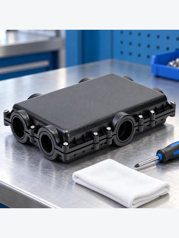
A splice box is an installation handover point and a future maintenance workspace. It needs to protect the joint while allowing technicians to identify fibres, reach the correct tray and restore the specified seal. In a blown-fibre network, this means planning cable entry, slack storage and re-entry before selecting an enclosure by its headline fibre count.
A splice box improves blown-fiber efficiency when its cable-entry layout, tray management, sealing approach, and access method match the network’s route and maintenance plan. At each transition, protect the joint, maintain the specified fibre bends and leave fibre identifiers accessible. IEC 61300 is a family of component test methods, not a blanket approval of every enclosure. Specify the enclosure and its accessories before installation, then verify the installed assembly against the project’s applicable requirements.
Why splice-box access affects installation time
A blown fiber installation separates the civil pathway from the cable placement operation: microducts are installed first, and fiber units are introduced later with air-assisted equipment. That staged model can speed expansion, but it also makes handover points critical. Every joint location must let technicians terminate, identify, test, and later re-enter the route without disturbing adjacent fibers.
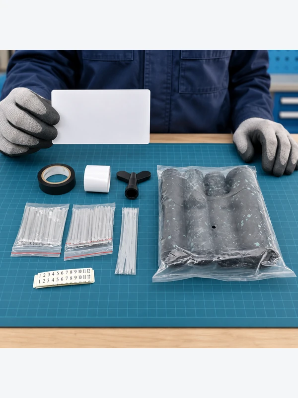
The entry, tray layout, slack storage and seals all affect installation and maintenance time. A practical design considers at least four interfaces—duct or cable entry, splice tray, slack storage, and sealing—because a fault at any one interface can turn a short service visit into a longer excavation, cable handling, or re-test event. Fiber geometry matters too: ITU-T G.652 and G.657 describe single-mode fiber characteristics, while the actual bend limits for a selected cable or fiber unit must come from its manufacturer documentation.
Why repeat visits increase splice-box costs
A second visit can expose access and labelling problems missed during installation. If identifiers cannot be read, trays cannot be lifted without tension, or a sealing component does not suit the incoming diameters, technicians spend time tracing fibers and repeating optical tests. For example, two extra technicians on a two-hour re-entry add four labor-hours before travel, traffic control, restoration, or customer-delay costs are considered. A clear tray map and repeatable installation sequence reduce that exposure; acceptance testing should follow the contract test plan, commonly including optical continuity and loss measurements.
Record tray changes and optical tests after reopening a closure
A later optical fault can be difficult to investigate if the closure was opened without a clear record. Before planned work, identify affected fibres and services, record the current tray map and follow the operator’s access procedure. Avoid disturbing unrelated circuits merely to make the layout look tidier. If the field arrangement differs from the drawing, resolve the identification before making a splice or moving slack.
After the authorised work, update the actual port and tray configuration and inspect the sealing arrangement as specified by the enclosure manufacturer. Record any replaced seals, accessories or damaged parts and the installation detail used. Environmental evidence belongs to a complete configuration: a result for one port and cable arrangement should not be silently transferred to a different entry method. Do not describe a pressure or optical check as proof of an unsupported IP rating.
Keep optical evidence separate from closure workmanship. The Fiber Optic Association explains that an OTDR can locate events and support comparison with a baseline trace, while direct insertion loss is measured using a source and power meter. Use the contract’s test plan and keep fibre identifiers, endpoints and settings with each result. A clear difference between a pre-work and post-work trace can guide investigation; it does not by itself identify every mechanical cause inside the enclosure.
For staged FTTH work, attach the updated enclosure record to the same route and address system used for activation. The FTTH planning article explains why a completed passive route is distinct from a provisioned customer service. Link the joint record with the microduct route guide and the selected HDPE microducts, so future work can trace both the optical path and the physical pathway. Using the same identifiers helps technicians locate the duct, closure and fibre involved in later work.
Compare enclosures by the work they must support
The right choice is the one that supports the network’s access strategy, rather than the largest enclosure on a catalogue page. The table below compares common planning approaches; it does not assign universal capacity or environmental ratings, which depend on the exact product and installed configuration.
| Planning approach | Operational advantage | Efficiency risk to control | Best procurement question |
|---|---|---|---|
| Compact distribution point | Shorter handling path for routine branch work | Limited working room can slow future changes | Can the tray arrangement support the expected number of accesses? |
| High-access joint location | Organized re-entry for growth and fault restoration | More parts can mean more installation variables | Which seals, ports, and accessories are included for the actual route? |
| Transition between pathway sections | Defines responsibility and test boundaries | Poor labeling creates tracing delays | How will route IDs, fiber IDs, and test records be retained? |
Size the splice point around access and fiber count
A fibre-optic splice-box specification should start with the physical job: indoor wall, chamber, pole, pedestal, or direct-burial context; the entering cable and duct construction; and the expected change frequency. Fiber count remains important, but it is only one of several dimensions. Procurement teams should ask for documented compatible ranges and installation instructions rather than infer fit from a photograph.
| Selection dimension | What to document | Why it improves field efficiency |
|---|---|---|
| Route architecture | Feeder, distribution, branch, and reserve paths | Prevents a handover point from becoming an unplanned bottleneck. |
| Entry and sealing | Incoming types, diameters, ports, and sealing procedure | Avoids mismatched components and repeat visits. |
| Fiber management | Tray count, routing path, slack method, and labeling convention | Helps protect bend control and speeds identification. |
| Maintenance model | Expected re-entry, tools, records, and access permissions | Aligns enclosure design with actual restoration work. |
Those choices also affect the rest of the pathway. Compatible микро хоолойн холбогчид help preserve a controlled duct route, while selected HDPE microducts should be considered as part of the same pathway and installation plan.
Check access to each tray before filling the enclosure
Nominal splice capacity does not establish whether a technician can reach a particular fibre after the enclosure is populated. Review the actual tray sequence, stored slack, cable entry and closure method for the supplied configuration. Use the manufacturer’s cable and fibre routing instructions, including the relevant bend limits, rather than applying one remembered radius to every buffer tube, bare fibre and jacketed cable in the box.
During design review, identify which tray will be opened for a later connection and what must move to reach it. Check that the intended operation does not place tension on a live fibre or require an uncontrolled bend at the tray hinge. Reserve the space and accessories needed for the defined expansion plan. An empty port or an unused position on a drawing is not sufficient if the installed cable and slack already obstruct the access path.
Confirm that the duct-to-cable transition is planned. A cable installed by air assistance must be handled, secured and routed using the approved instructions after it reaches the access point. Do not assume that the enclosure is a pressurised blowing manifold or that its lid can be left open during a process it was not designed to support. The blowing equipment page helps identify the separate installation stage; the enclosure documentation defines its own cable-entry and sealing arrangement.
Make the first completed assembly a controlled workmanship example when the project requires one. Record port use, tray identifiers, fibre assignments, slack location and the instructions used. A proposed re-entry review can then ask whether the next technician can identify and access the required fibre without disturbing neighbouring services. Treat that as a project acceptance check, not as a claim that a particular enclosure has passed an undocumented universal serviceability test.
Which standards cover splice-closure tests and performance
Check the scope of the cited standard and the tested enclosure configuration. The IEC 61300 series specifies test and measurement procedures for fiber-optic interconnecting devices and passive components; a cited IEC 61300 method describes how a stated characteristic is evaluated, not automatic certification of a complete installed assembly. IEC 61753 provides performance-standard frameworks for passive fiber-optic components, while Telcordia GR-771 is widely used as a generic requirement reference for fiber-optic splice closures in telecommunications applications.
For fiber compatibility and system planning, ITU-T G.652 and G.657 address optical fiber characteristics. They do not, by themselves, validate enclosure sealing, installation quality, or local safety requirements. The applicable evidence depends on the destination market, installation environment, customer specification, and every claim made in a tender or product sheet. Unsupported IP, capacity, or certification claims create commercial risk: they can trigger submittal rejection, retesting, or disputes over responsibility.
A practical buying checklist for contractors and OSP teams:
- Map each splice point to the route drawing and identify whether it is a one-time joint or a likely re-entry location.
- Request installation instructions, compatible accessory lists, and test evidence that is specific to the offered configuration.
- Confirm fiber routing, slack storage, labels, and the technician’s working sequence before field deployment.
- Retain acceptance records with route identifiers.
ANMASPC / Microduct Connector can support this specification stage by helping buyers align pathway components, connection hardware, and cable-blowing equipment documentation with the intended installation process. Request the drawings, accessory list and instructions that installers will need to assemble and later reopen the enclosure.
Олонтаа асуугддаг асуултууд
What is a fiber optic splice box?
A fiber optic splice box is an enclosure and fiber-management system that protects and organizes spliced optical fibers at a network joint or distribution point. Its suitability depends on the cable types, environment, access needs, and installation instructions for the specific assembly.
What is the difference between a splice box and a splice closure?
A splice closure generally emphasizes environmental protection around a fiber joint, whereas “splice box” is often used for an enclosure that also emphasizes organized access and distribution. Market terminology varies, so buyers should compare the supplier’s drawings, sealing method, and approved application instead of relying on the name alone.
Why are splice boxes used in blown fiber installation?
They provide a controlled point for joining, identifying, testing, and managing fibers where a blown-fiber route transitions or branches. In a growing fiber network, that organization can reduce re-entry time and lower the chance of disturbing live circuits.
How do you choose a fiber optic splice box?
Start with the route architecture, incoming cable and duct details, expected fiber management, environmental exposure, and maintenance model. Then verify the exact configuration against installation instructions and the project’s required test evidence.
Can a splice box be used outdoors?
Some enclosure configurations are intended for outdoor use, but outdoor suitability must be confirmed from the manufacturer’s documentation for the installed ports, seals, and mounting arrangement. Check the project’s environmental exposure and local requirements before specifying it.
How many fibers can a splice box hold?
Capacity varies by enclosure, tray design, splice type, cable construction, and reserve-space requirement. Use the supplier’s documented capacity for configuration, and leave management space for the access plan rather than selecting by a headline count.
What evidence should be requested for an outdoor splice enclosure?
Request the applicable environmental test scope, sealing and cable-entry instructions, fiber capacity and bend limits, mounting details, identification method, re-entry procedure and replacement-part information for the exact model.
Does the advertised splice count guarantee room for later additions?
No. Usable expansion depends on the installed cable entries, tray layout, slack storage, accessories and access sequence. Check the populated configuration and manufacturer’s instructions, then reserve the space required by the actual expansion plan.
What should be recorded after opening and resealing a splice closure?
Retain the route and closure IDs, changed fibre assignments, port and tray configuration, replaced seals or accessories, inspection result and the optical tests required by the contract. Keep test endpoints and settings so a later technician can compare like with like.
Дүрийн баримжаа
Summary
A splice point needs accessible trays, readable fibre identifiers and a sealing arrangement that technicians can restore after maintenance. Select the enclosure with its actual cable entries, tray sequence, slack requirements and sealing arrangement in view. Confirm the relevant bend limits from the supplied documentation, and review how a later tray operation will affect neighbouring fibres. After re-entry, update the port and fibre map, record replaced sealing parts and retain the required optical results against the same route identifiers. Keep enclosure workmanship, environmental evidence and optical acceptance distinct. These records help technicians identify the affected fibre and inspect the work completed at the last visit.