
When field supervisor Daniel in Manchester joined two microduct sections in this illustrative scenario, the team pushed both ends into the coupling and pressurized the route. Within minutes, the gauge fell and leak-detection fluid bubbled at the joint. Replacing the connector did not solve it: the cut was angled and the duct outside diameter did not match the ordered part. The apparent product failure was actually a sizing and preparation failure.
Resumen: A Microduct Connector For Fibre Optic Cable succeeds when the connector matches the duct outside diameter, both ends are cut square and fully inserted, and the assembled route passes the documented test for that exact part. ITU-T L.108, published in 2018, covers characteristics and tests for blown microduct cable systems, but it does not create one universal connector pressure or hold time. Verify the drawing, environmental evidence and test procedure before procurement, then record the result before blowing fiber.
How the Connector Supports Fibre Blowing
A microduct connector keeps the pathway continuous between duct sections. In a push-fit design, gripping components retain the duct while an O-ring arrangement limits leakage. A transparent body can show insertion position, but it does not prove that the duct is round, correctly sized or sealed.
The connector belongs to a system, not to the optical fiber itself. ITU-T L.108 addresses fibre units, microcables, microducts and blowing tests; IEC 60794-5-20:2014 covers outdoor elements installed by blowing. Coordinate the connector with the microducto de HDPE, cable, equipment, route and project specification.
Match the Connector to the Duct Dimensions
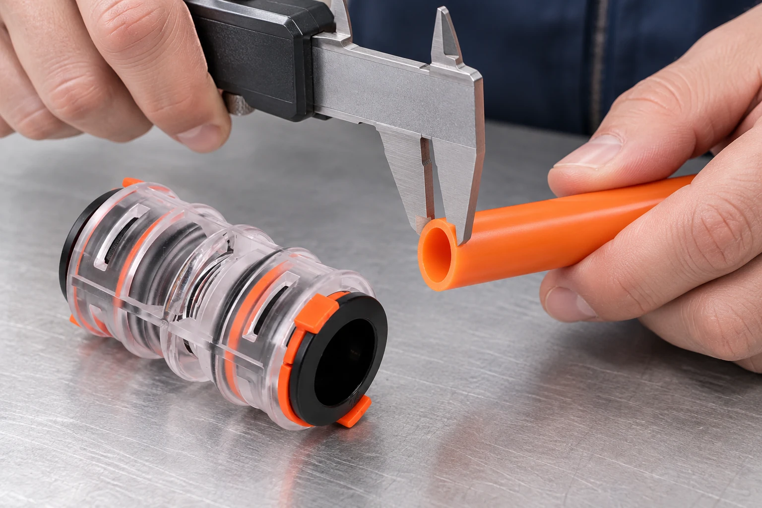
Connector fit is normally governed by microduct outside diameter; inside diameter helps confirm cable clearance. Record both dimensions, material, condition and tolerances. Product ranges vary: Hexatronic publishes connectors for 3 to 20 mm microducts, while Dura-Line lists straight and transition sizes starting at 5 mm. These examples do not prove cross-brand compatibility.
A straight connector joins equal specified outside diameters; a reducer joins two documented sizes. Do not force a similar tube into a port, wrap it to increase diameter or infer fit from inside diameter. Release a Microduct Straight Connector For Fibre Optic Connector for purchase only when the connector drawing and duct data sheet agree.
Mismatch costs include route isolation, repeated tests, crew delay and reopening access. An illustrative TCO review should compare connector and inspection cost with the project-rate cost of one failed joint.
Prepare and Seat the Push-Fit Connector Correctly
Depressurize the route. Inspect the port and duct for dirt, scratches, flattening or burrs. Cut the duct square with the specified tool, remove debris and mark the required insertion depth. Push straight to the documented stop, avoid side loading and fit the locking clip when supplied.
Dura-Line describes its micro-couplers as tool-free for assembly and disassembly and tested to EN 50411-2-8:2009; that applies only to the cited family. For another Micro Duct Optical Connector, follow its instructions. Unapproved lubricant can contaminate the air path or alter seal performance.
Before blowing, isolate the section and use calibrated equipment. The air-blowing overview provides context, but the data sheet and approved method control pressure, stabilization, hold time and acceptance. Do not transfer Dura-Line’s published 16 bar figure to an undocumented connector.
Check Seals and Environmental Limits Before Outdoor Use
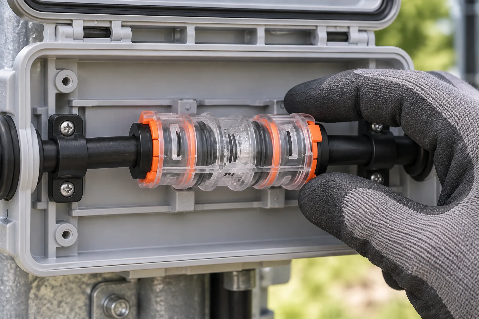
O-rings can leak because of debris, burrs, scored or oval duct, or ageing beyond stated limits. On a clean, depressurized joint, follow the service instructions. Replace seal components only under an approved procedure; replace the connector when seal condition is uncertain.
Outdoor suitability cannot be inferred from color or resin name. ITU-T L.108 identifies temperature cycling, ageing, water and UV tests in the broader blown-system context. Request the exact part’s temperature range, UV method and duration, installation category and dated evidence. IEC 60794-5-20:2014 alone does not certify every connector.
For FTTX microduct connectors, map each building-entry, chamber, aerial or buried joint and require evidence for its actual exposure. “FTTx compatible” alone does not address water, sunlight, thermal cycling or fire requirements.
Choose Between a Straight and Reducer Connector
| Factor de decisión | Straight connector | Reducer or transition connector |
|---|---|---|
| Geometría del conducto | Joins the same documented outside diameter | Joins two different documented outside diameters |
| Typical decision | Continue a uniform duct run | Manage an approved size transition |
| Compatibility check | Verify one port size, duct tolerances and material | Verify both port sizes, both ducts and any orientation rule |
| Installation risk | Wrong nominal size or incomplete insertion | Reversed ports, unsupported size pair or incomplete insertion |
| Mantenimiento | Inspect one equal-size joint configuration | Record which size is connected on each side |
| Tendencia del costo unitario | Often simpler, but quotation controls | May be more specialized; quotation controls |
| TCO focus | Repeatability on uniform routes | Avoiding improvised adapters and leak points |
Match the Connector Evidence to the Route Conditions
| Condición de aplicación | Connector decision | Evidence to request before approval |
|---|---|---|
| Indoor or protected | Match sizes and access needs | Drawing, temperature range and applicable fire documents |
| Outdoor above ground | Specify solar and weather exposure | UV method and duration, temperature range and sealing report |
| Handhole or wet chamber | Confirm water exposure category | Water-ingress method, pressure procedure and inspection plan |
| Direct buried | Use a documented burial configuration | Burial statement, mechanical and sealing evidence |
| Different duct sizes | Specify a reducer by both outside diameters | Port-by-port drawing, tolerances and approved duct material combinations |
| Fiber blowing section | Coordinate joints with the blowing plan | Working and test limits, stabilization, hold time and acceptance |
Use Standards to Define the Test Scope
- ITU-T L.108 (2018): specifies characteristics and tests for microduct fibre units and microduct cables installed by blowing; it is not a universal connector certificate.
- IEC 60794-5-20:2014: covers outdoor microduct fibre units, microducts and protected microducts. Confirm which clauses apply to the purchased assembly.
- EN 50411-2-8:2009: is cited by Dura-Line for its micro-coupler family and by the Oulu page as a product-family statement. A citation does not prove every model has identical performance.
Unsupported claims can cause rejected submittals, retesting or handover delays. Identify each document as a specification, test method, supplier declaration or certificate; applicability depends on market, environment and intended use.
Complete These Five Checks Before Ordering
- Provide duct outside and inside diameter, material, tolerance and condition for both sides.
- Classify each location and state project and local requirements.
- Request the exact drawing, instructions and current pressure, temperature and UV evidence.
- Approve test limits, stabilization, hold time and acceptance criteria.
- Trial the connector with actual duct and document the result before volume ordering.
Oulu / ANMASPC, a China-based B2B microduct connector manufacturer, can be asked to map its configurable connector options to the buyer’s duct dimensions and documentation list. Review the published conector recto para microducto as a starting point, then confirm every model-specific statement in the quotation and current technical file.
Preguntas frecuentes
How do you install the Microduct Connector For Fibre Optic Cable without causing an air leak?
Depressurize the route, confirm the duct outside diameter, make a clean square cut, remove debris, mark the specified insertion depth and push the duct straight to the documented stop. Fit any supplied locking clip and test the isolated section by the approved method. If it leaks, inspect sizing, cut quality, surface damage, ovality, contamination and seal condition before replacing parts.
What pressure and time should be used to test the Microduct Connector For Fibre Optic Cable?
There is no safe universal pressure or hold time for every connector and route. Use the lower applicable limit from the exact connector documentation, duct documentation, project method and test equipment, including any specified stabilization period and acceptance criterion. A rating published for another manufacturer’s product family is not transferable.
Can the Microduct Connector For Fibre Optic Cable be reused after the duct is disconnected?
Only when the manufacturer’s instructions permit reuse and inspection shows no damage to the body, gripping parts, release mechanism or seal. Replace the connector if release has scored the duct or seal, if contamination cannot be removed by the approved method, or if the reassembled joint fails its specified test.
Which material and UV rating are best for outdoor Microduct Connector For Fibre Optic Cable applications?
No material name or universal UV label is “best” for every route. Specify the exposure, temperature range and service environment, then compare exact-part UV test methods, durations and acceptance criteria. Request current evidence instead of inferring performance from color or resin type.
Why does the Microduct Connector For Fibre Optic Cable leak during or after fiber blowing?
Common causes include the wrong port size, an angled or burred cut, incomplete insertion, scored or oval duct, seal contamination, side loading, damaged O-rings or operation beyond documented limits. Isolate and depressurize the route before diagnosis; verify the joint and adjacent duct rather than assuming the connector alone is at fault.
Do you need tools or lubricant to fit the Microduct Connector For Fibre Optic Cable correctly?
A suitable duct cutter, measuring tools and approved test equipment may be needed, although many push-fit connectors require no tool for insertion. Do not apply lubricant unless the exact connector and duct instructions authorize a compatible product and method. The related FTTH microduct guide provides additional network context.
What Fibre Installers Should Confirm Before Installation
The connector is one controlled point in the blowing route, so the usable choice depends on duct dimensions, straight or reducer geometry, clean preparation, seal protection and an approved test. Temperature, UV exposure, pressure, hold time and reuse remain exact-part questions; a rating from another manufacturer cannot be transferred. The 12 mm interface guide helps structure the dimensional check, while the FTTH fittings comparison keeps a general fitting label from replacing a defined function. In the Manchester example, correcting the cut and size selection addresses the likely cause before another blowing attempt.
Referencias
- ITU-T L.108: Optical fibre cable elements for microduct blowing-installation application.
- IEC 60794-5-20:2014: Outdoor microduct fibre units, microducts and protected microducts for installation by blowing.
- Hexatronic Fiber Solutions: Microduct Connectors and End Stops.
- Dura-Line: Micro Couplers.
For fibre installers, the useful sequence is clear: measure the duct, select the correct straight or reducer geometry, prepare clean square ends, protect the seal, confirm insertion and test the assembled route. Pressure, temperature, UV exposure and reuse remain questions for the exact part and project—not values to borrow from another catalogue. When those records are complete, the connector becomes a controlled part of the blowing route rather than an assumption hidden inside it.


