
When a fiber-installation supervisor in Leeds encountered a hissing joint while preparing an FTTx route for a blowing run, the crew first increased the compressor setting; the gauge still fell rapidly and the cable would not advance. The visible failure looked like a bad fitting, but a caliper check and a closer look at the cut ends showed the real causes: one nominally matching duct was oval and the other had not been pushed to its stop. Re-cutting the ducts and selecting the coupling for their measured dimensions restored the seal.
The short answer is: Most leaking microduct couplings are corrected by measuring the duct outside diameter (OD), making a square clean cut, fully seating each end, and carrying out the pressure-and-hold test required by the duct system and connector manufacturer. There is no universal field pressure or hold time: the valid value is the lower applicable system limit and the project’s documented acceptance method. For air-blown optical-fibre routes, IEC 60794-5-20 provides the relevant system context; a test method or standard reference is evidence to review, not a substitute for a compatible assembly.
A microduct coupling is the in-line interface that must retain the duct while keeping its air path continuous. It may be described as a micro-duct coupling, a straight connector, a union, or a reducer. Procurement searches also use Microduct coupling and Microduct couplings optical fiber; the useful selection inputs remain duct OD, wall construction, material, pressure duty, and environment.
Find the leak before changing the blower settings
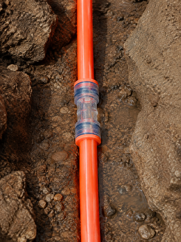
Start with the joint, not the compressor. Isolate and safely depressurize the section, then inspect for incomplete insertion, an off-axis tube, an angled or crushed cut, grit, a split body, or bending load. A transparent body or witness window helps confirm seating, but cannot prove a clean seal or compatible duct.
Then rebuild the suspect joint using the fitting manufacturer’s release and insertion instructions. Cut the HDPE squarely with a suitable cutter, remove loose swarf, wipe the outside surface with a lint-free cloth, and keep contaminants out of the bore. Push the duct straight into a tool-free push-fit body until it reaches the stated stop; twisting, prying with pliers, or forcing an oval duct through the collet can damage the seal. Finally, repeat the documented leak test before approving the route for fiber blowing.
| Observed symptom | Likely cause | Corrective action | Acceptance check |
|---|---|---|---|
| Pressure drops immediately | Duct not fully seated, damaged O-ring, or wrong OD | Depressurize; inspect, recut, replace damaged parts, and fit the specified size | Insertion mark at body; repeat project pressure hold |
| Leak appears only when the duct is moved | Side load, unsupported bend, or incomplete collet engagement | Realign and support the duct; replace a damaged coupling | Joint stays stable during the approved inspection movement |
| Cable stalls near a joint | Burr, internal step, or unsuitable reducer transition | Inspect the ends and use a listed straight or reducer fitting | Documented bore continuity and successful system test |
| Repeated leaks after outdoor exposure | UV, temperature, or moisture duty was not specified | Review the exact body and seal environmental data; replace affected parts | Supplier documentation matches the site envelope |
Match the coupling to the duct, not the nominal label
The most useful microduct connector size guide starts with the duct datasheet and a field measurement. Record OD in more than one orientation when a duct has been coiled or flattened; record ID and wall thickness too. A “12 mm” coupling is appropriate only for its defined OD tolerance and wall range.
Choose a straight coupling for compatible like-for-like joints and a purpose-designed reducer when specified ODs differ. A reducer does not correct an out-of-tolerance duct: each end still needs proper seal engagement and a transition suitable for the planned cable and blowing head. This matters in mixed FTTx and telecom duct inventories.
| Duct marking to verify | Coupling choice | What to measure or confirm | Typical network use |
|---|---|---|---|
| Same nominal OD at both ends | Straight coupling | Actual OD, wall range, material, insertion depth | Continuous access or distribution microduct |
| Different specified ODs | Reducer connector | Approved range for each end and transition bore | Planned transition between duct sections |
| Unknown or oval duct | Do not select from label alone | Caliper readings at several orientations; duct condition | Repair, legacy route, or site stock |
| Exposed or chamber installation | Application-specific straight or reducer fitting | UV, temperature, moisture, impact, and support needs | Outdoor FTTx, telecom cabinets, and access pits |
The table is a decision aid, not an approval chart. Use the exact product drawing and duct-system documentation to determine the permissible range. For a broader overview of fitting types, see what a microduct connector does and the site’s guidance on choosing the right connector.
Protect O-rings and seals through installation and maintenance
O-rings and similar seals need a clean, undamaged duct surface at the intended compression. Check for nicks, flattening, grit, displaced seals, cracked collets, and body damage. Do not use lubricant, solvent, tape, or sealant unless the documentation expressly permits it.
Replace a seal or fitting after a persistent failed test, or whenever the body, collet, or seal is damaged. Treat a released push-fit fitting as non-reusable unless its maker provides an inspection-and-reuse procedure. Approved spares cost less than reopening a route after cable installation.
For outdoor routes, specify body and seal temperature range, UV/weathering evidence, and direct-exposure limitations—not a generic “outdoor rated” claim. Thermal movement and sunlight add stress at unsupported joints. The installation and maintenance guidance for HDPE microduct helps when the fault originates upstream.
Compare selection approaches by installed value
| Selection approach | Installation efficiency | Leak and compatibility risk | Maintenance and TCO tendency |
|---|---|---|---|
| Nominal size only | Fast at first | High when OD tolerance or duct condition differs | More troubleshooting, compressor time, and potential revisits |
| Measured duct with specified straight coupling | Tool-free installation after preparation | Lower when the approved range and seating are verified | More predictable acceptance and fewer avoidable interventions |
| Verified reducer for planned transition | Moderate; two ends require checks | Lower than forcing a straight fitting across different sizes | Supports controlled mixed-duct designs |
| Documented outdoor assembly | Similar field effort | Lower environmental uncertainty | Better basis for lifecycle and replacement planning |
The unit price is only one cost input. An illustrative calculation should include leak-finding time, compressor operation, a lost blowing slot, access controls, and the risk of disturbing installed cable. Measurement and an approved acceptance test can prevent failure at the most expensive stage—after mobilization.
Use standards as evidence, not as a product badge
IEC 60794-5-20 addresses outdoor microduct systems for blown optical-fibre cables and helps define the system context for FTTx routes. IEC 61300-2-34 is a resistance-to-air-pressure test method for fibre-optic interconnecting devices and passive components; it is not a blanket certification for every coupling. Likewise, the scope of ISO 13477-1 must be checked against the material, assembly, and test objective in the project specification.
For tenders and incoming inspection, request the drawing, approved duct range, test configuration, pressure, hold time, temperature, and acceptance criterion. State the market and installation environment before requesting UV, temperature, or compliance documentation. Unsupported claims can delay approval and create an avoidable responsibility gap.
Five procurement actions before a blowing window
- Freeze the duct schedule first: OD, ID, wall, material, route location, and known tolerance.
- Map each like-size joint to a straight fitting and each planned change in OD to an approved reducer.
- Require a field method statement for cutting, cleaning, insertion-depth checking, support, and leak testing.
- Specify outdoor UV and temperature conditions, plus the evidence needed for the exact body and seal.
- Keep traceable spares and define whether a disconnected fitting or seal may be reused.
Microduct Connector can help procurement teams compare configurable fittings, drawings, and requested technical documentation against an actual duct schedule. Before standardizing a bill of materials, review the practical difference between straight connectors and couplers and provide the supplier with the acceptance test your network owner expects.
What should a leak-troubleshooting record contain?
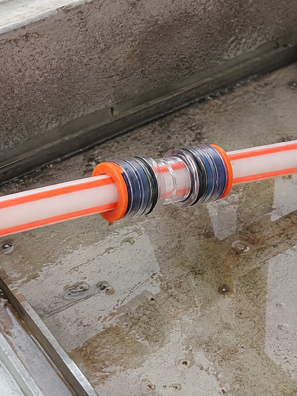
For recurring leaks, the useful unit of evidence is the complete joint, not just the coupling body. Log the duct OD on each side, cut angle, insertion mark, seal condition, lock position, route location, air medium, test method and the action taken. Comparing those fields across failed and successful joints often reveals an installation pattern that a pressure gauge alone cannot show.
Keep the connector fundamentals guide, connector selection guide and HDPE microduct range linked in the work package so field teams can confirm the interface before retesting.
Frequently asked questions
How can installers visually check that the microduct couplings is fully seated?
Use the manufacturer’s insertion mark, transparent body, or inspection window where provided, and confirm the duct has reached the specified stop. The duct should enter squarely without a visible gap or off-axis load. Visual confirmation supports, but does not replace, the required pressure test.
When should the seals or body of the microduct couplings be replaced?
Replace them when inspection finds a nicked, displaced, flattened, or contaminated seal; a cracked body; damaged collet; or a persistent leak after correct preparation. If the fitting has been disconnected, follow the manufacturer’s explicit reuse procedure; otherwise a new, compatible assembly is the safer choice.
Where can installers use the microduct couplings in fiber and telecom networks?
They are used for in-line duct continuity in FTTx access routes, telecom distribution sections, cabinets, handholes, building entries, and repair locations. The exact model must match the duct, pressure duty, exposure, and any project requirement for bore continuity or gas blocking.
How do you choose the correct duct diameter for the microduct couplings?
Measure the duct OD and check the fitting’s approved gripping and seal range; also confirm ID, wall thickness, material, and ovality when the datasheet requires them. Use a straight fitting for compatible like-size ducts and a listed reducer for two different specified ODs. Never select solely from a nominal label.
How do you install the microduct couplings without causing an air leak?
Depressurize the line, make a square burr-free cut, clean the duct, inspect the seal, and push the duct straight to the stated stop using the tool-free method where the product provides it. Protect the joint from side load, then perform the project’s documented pressure-and-hold test before blowing fiber.
What pressure and time should be used to test the microduct couplings?
Use the pressure, stabilization period, and hold time specified for the complete duct system by the project owner and applicable manufacturer instructions, without exceeding the lower relevant limit. Record the test setup, temperature, start and finish values, and acceptance criterion. A value copied from another coupling or a generic internet guide is not a safe substitute.
Should a crew raise compressor pressure when a microduct coupling leaks?
Not as a first response. Isolate the section and inspect dimensions, cuts, insertion, seals and locking. Raising pressure can exceed an approved limit and may conceal the fitting or duct-preparation problem.
When is replacement better than cleaning and reseating a coupling?
Replace it when the body, seal or lock is damaged, the part is outside its approved reuse instruction, or the joint still fails after verified preparation. Record the reason so the replacement is traceable.
References
- ASTM F2164: Field leak testing of polyethylene pressure pipingOfficial ASTM page; leak-test method reference.
- ITU-T L.156: Optical fibre cable installation by air assistanceOfficial ITU recommendation page; air-assisted installation context.
- ISO 12100: Safety of machinery – risk assessment and risk reductionOfficial ISO page; stored-energy and risk-control boundary.
The dependable rule is simple: measure the duct, seat the seal, prove the joint, then blow the fiber. When your team is ready to qualify a fitting for a new or repaired route, explore the Microduct Connector microduct connector range and contact the team with the duct schedule, environment, and acceptance criteria for a focused compatibility discussion.


