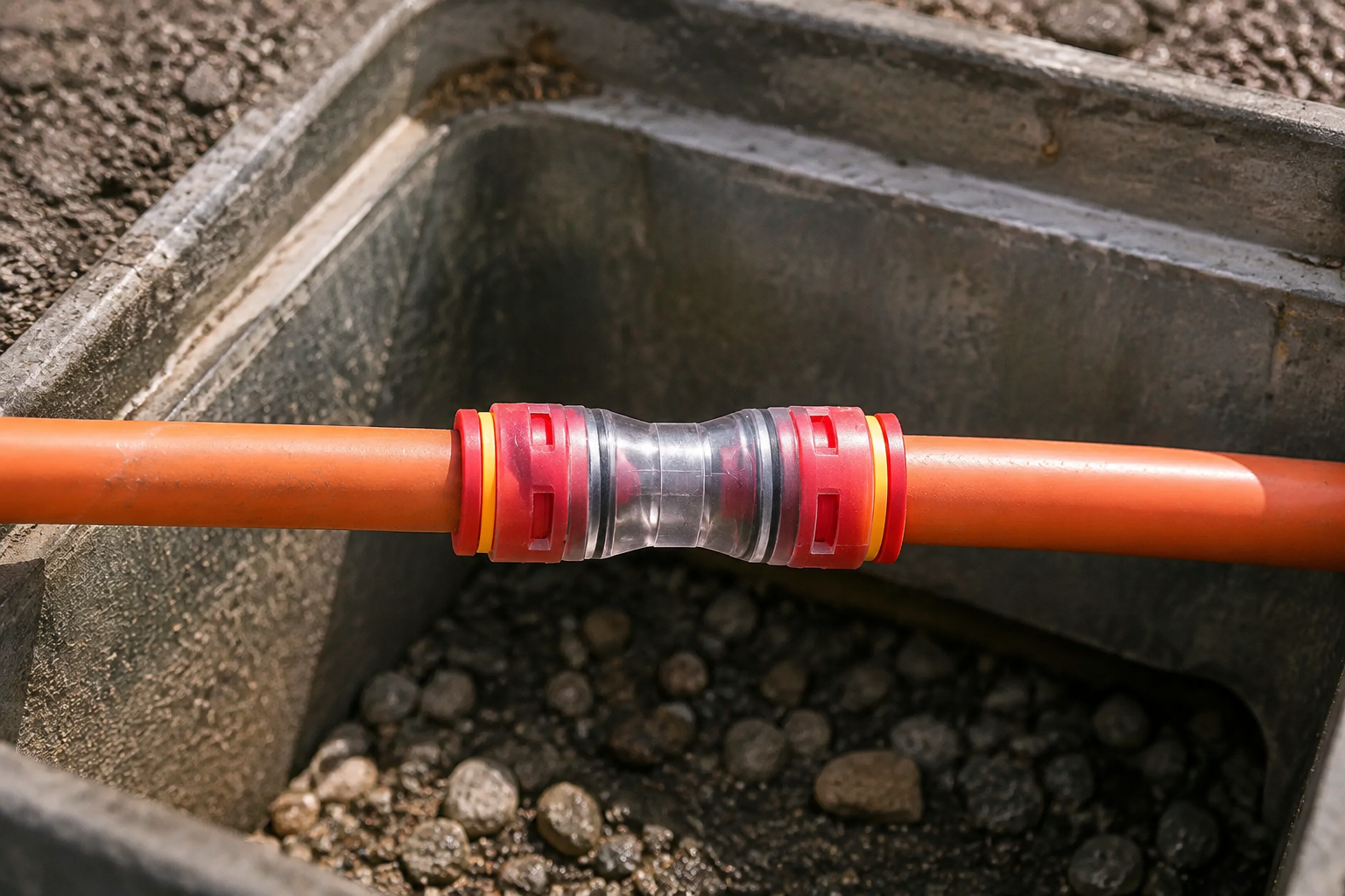
When a field supervisor in Manchester connected a 12 mm HDPE microduct to a nominally “12 mm” fitting, the pressure gauge fell within seconds and the fiber-blowing crew stopped. A closer inspection found that the duct’s measured outside diameter and wall tolerance did not match the connector’s gripping range; the product itself was not defective. Re-cutting the duct square and selecting the specified size restored a stable seal.
Summary: Reliable Microduct Connectors depend on measured duct outside diameter, clean preparation and a documented pressure test—not on nominal labels alone. Specify a connector to the duct manufacturer’s tolerance, install it to the supplier’s instructions, and verify the joint against the project pressure class using a defined hold time. EN 50411-2-8 and IEC 60794-5 provide useful framework for connector and microduct performance; buyers should request the applicable test reports before approving a batch.
Why sizing controls air-blown fiber performance
A microduct joint must preserve the duct’s bore while resisting axial pull, vibration and compressed air. Correctly specified Microduct Connectors keep the seal energised; a connector that is too large may leak, while one that is too small can ovalise or score the HDPE. Either condition increases air loss, lowers the pressure differential that moves the cable and adds compressor runtime. In a long route, a small leak repeated at every handhole becomes a measurable total-cost issue.
Build a microduct connector size guide from the actual duct datasheet: outside diameter (OD), inside diameter (ID), wall thickness, ovality and allowable temperature. Record measurements from a sample of each reel; do not infer OD from the cable count. For a reducer, verify both ends independently and confirm that the transition does not create a step that can snag a blowing head. In some tenders the same part is written as a micro duct connector, so map terminology to the measured dimensions.
HDPE preparation and installation sequence
Prepare a square, clean end
Cut the HDPE with a guided tube cutter so the face is perpendicular to the axis. Remove burrs, mud and ovality; wipe with a lint-free cloth and keep the bore free of lubricant or tape. If the duct has been stored in a coil, allow it to relax and check that the end has not flattened. Mark the insertion depth supplied by the connector manufacturer.
Seat the seal without damaging it
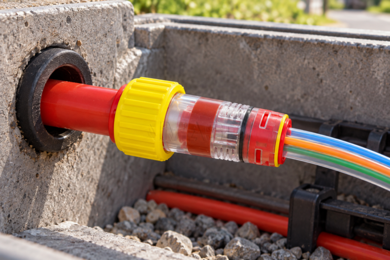
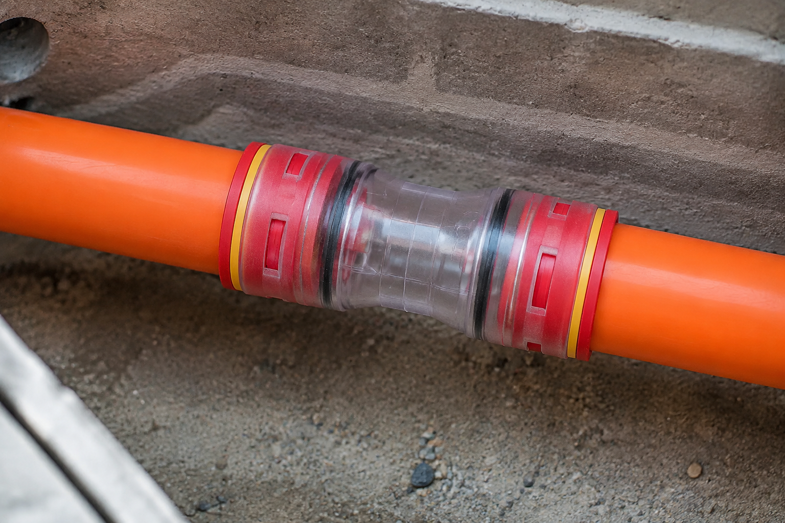
Push the duct fully home in a straight line until the depth mark reaches the body. A transparent body is valuable because an installer can see the duct pass the seal and confirm that the collet has engaged. Do not twist the duct under load, use pliers on the body or mix seal materials. Secure the assembly against bending at the entry and respect the minimum bend radius of the duct.
For a practical Microduct Connector installation checklist, inspect: square cut, clean bore, insertion mark, visible seal engagement, locked collet and strain relief. Photographing these points at representative chambers creates a useful handover record for network operators and confirms that each Microduct Connector was seated consistently.
Pressure and leak testing that finds the root cause
Test the completed section before fiber blowing. Isolate the segment, fit a calibrated gauge near the test point and raise pressure gradually to the lower of the duct system’s design test pressure or the connector’s rated limit. Follow the project method statement and the connector supplier’s instructions; standards define performance methods, but they do not replace the pressure class specified by the network owner. A documented micro duct connector test makes acceptance consistent across crews.
- Stabilise the air temperature and allow the pressure to settle after pressurisation.
- Record starting pressure, ambient temperature, segment length and isolation time.
- Hold for the specified period—often a short acceptance hold, but always the period in the contract or manufacturer procedure—and record the final pressure.
- Use an approved leak-detection fluid or an ultrasonic probe at each joint; never introduce liquid into an open fiber path.
- If pressure decays, isolate halves of the route to narrow the search, then repeat the test after correcting the joint.
For procurement, ask for test reports showing the pressure, duration, temperature and sample configuration. A pass/fail statement without those fields cannot be compared across suppliers. The same discipline protects fiber-blowing performance: stable pressure means predictable cable speed and less wasted compressed air.
Material, environment and lifecycle choices
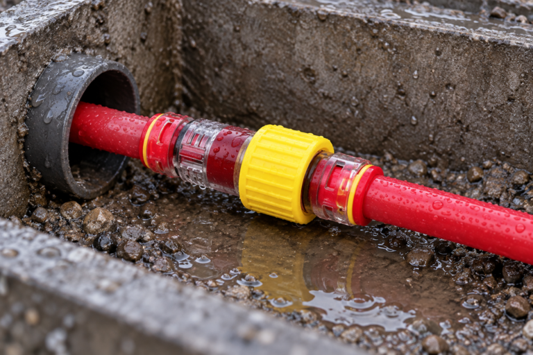
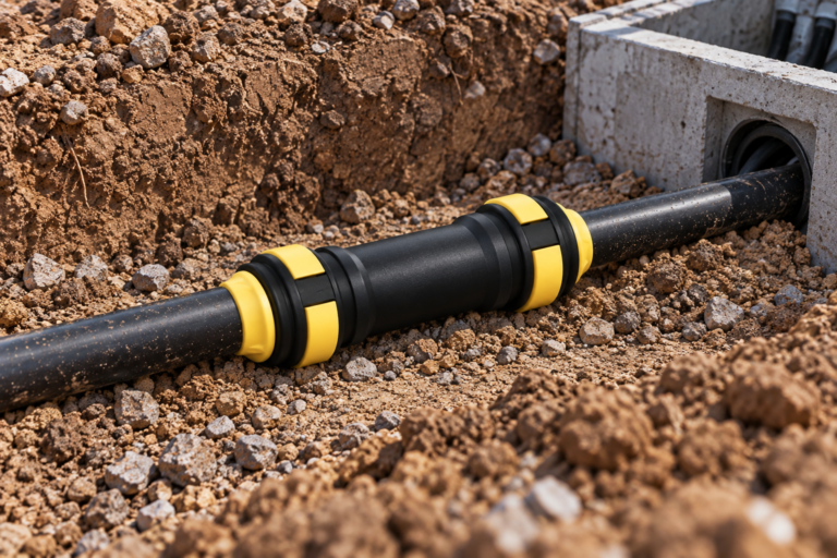
Most telecom microduct systems use HDPE duct with an engineering-polymer connector body and elastomeric seals. Specify compatibility with the duct resin, installation lubricant (if permitted), cleaning agents and the expected temperature range. For direct-buried chambers or exposed risers, require UV-stabilised materials and a documented weathering or UV rating; ETSI EN 300 019 can help classify environmental conditions, while the connector datasheet should state its own limits. Outdoor Micro duct Connectors should be approved for the site’s UV and temperature envelope, not selected by colour.
Transparent bodies support inspection, but clarity is not a substitute for mechanical data. Check wall thickness, burst or pressure rating, pull-out performance and seal temperature range. A connector disconnected from a duct should normally be treated as a consumable unless the manufacturer explicitly approves reuse; seals can take a compression set and collets may lose holding force. Replacement is usually cheaper than troubleshooting a concealed leak after cable installation. The same rule applies when a spare Microduct Connector has been stored on a truck: inspect it before use.
Value comparison for project buyers
| Selection approach | Air-tightness risk | Installation effort | Lifecycle effect |
|---|---|---|---|
| Nominal size only | High when OD tolerances differ | Appears low; rework is likely | Higher compressor use and call-outs |
| Measured OD/ID with tolerance check | Low when preparation is controlled | Moderate; requires gauge and records | Predictable blowing and fewer returns |
| Reducer selected from verified end sizes | Low if transition is smooth | Moderate; inspect both seals | Supports mixed duct inventories |
| UV-rated, documented material | Stable in specified exposure | Same basic sequence | Lower replacement risk outdoors |
Dimension-based decision matrix
| Project dimension | What to verify | Evidence to request |
|---|---|---|
| Duct geometry | OD, ID, wall, ovality and tolerance | Current duct datasheet and sample measurements |
| Pressure duty | Operating and test limits for the complete route | Rated-pressure and leak-test report |
| Outdoor exposure | UV, temperature, moisture and impact conditions | Material declaration and environmental rating |
| Field process | Cutting tools, insertion depth and inspection access | Installation instruction and training record |
| Lifecycle | Approved reuse policy and spare strategy | Replacement recommendation and warranty terms |
Standards and compliance checkpoints
EN 50411-2-8 addresses microduct connectors used in optical-fibre systems; EN 50411-2-5 covers gas-block connectors. IEC 60794-5 sets requirements for microducts, and the EN 61300 series describes fibre-optic component test methods. These are technical standards, not automatic certification marks: the buyer should verify the exact edition, scope and test configuration. Any Micro duct Connectors claim in a tender should point to that evidence.
For quality systems and market access, Oulu / ANMASPC reports ISO 9001 and ISO 14001 management systems plus CE and RoHS documentation for applicable products. Applicability depends on destination market and product construction; request declarations, rather than assuming every connector carries every mark. Unsupported compliance claims can delay acceptance, trigger corrective action or create liability for the importer.
Five procurement actions that prevent leaks
- Freeze the duct specification first, then map each OD range to a connector SKU.
- Approve a first-article sample using measured insertion force, visual seal engagement and a documented pressure hold.
- Include cutting, cleaning and inspection steps in the contractor method statement.
- Define outdoor UV and temperature requirements in the purchase order, not in a later site query.
- Buy a small spare allowance and state whether disconnected fittings may be reused.
Oulu / ANMASPC (Zhejiang Oulu Automatic Equipment Co., Ltd.) has manufactured microduct connectors and pneumatic components since 2003, with stated exports to more than 40 countries and 30+ patents/designs. Buyers can compare options in the microduct connector category, including straight connectors, reducers and gas-block connectors.
FAQ
Where can installers use the Microduct Connectors in fiber and telecom networks?
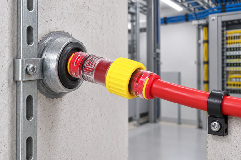
Installers use them at handholes, cabinets, building entries, FTTx distribution points and repair joints where HDPE microduct sections must remain air-tight. Select a body and seal system rated for the route’s pressure, burial or exposure conditions.
How do you choose the correct duct diameter for the Microduct Connectors?
Measure the duct OD, ID and ovality, then match those values—not just the printed nominal size—to the connector’s gripping range. Confirm both ends separately on a reducer and retain the measurement record with the purchase order.
How do you install the Microduct Connectors without causing an air leak?
Cut square, deburr and clean the HDPE, mark insertion depth, push the duct fully home and verify seal and collet engagement through the body where possible. Support the joint against bending and test before blowing fiber. This sequence applies whether the catalogue calls the part a micro duct connector or a push-fit microduct fitting.
What pressure and time should be used to test the Microduct Connectors?
Use the lower of the network test pressure and the connector’s rated limit, with the stabilisation and hold time specified by the project or manufacturer. Record pressure, temperature and duration; there is no universal value that safely covers every duct system.
Can the Microduct Connectors be reused after the duct is disconnected?
Only when the manufacturer’s instructions explicitly permit reuse and inspection confirms undamaged seals, collets and body. Otherwise install a new connector; a low-cost replacement avoids hidden leaks after cable placement.
Which material and UV rating are best for outdoor Microduct Connectors applications?
Choose an engineering-polymer body and elastomer seal compatible with HDPE, rated for the site temperature and UV exposure. Ask for the material declaration, UV or weathering evidence and pressure data for the exact SKU. Treat every Micro duct Connectors purchase as a traceable lot with a stated environmental rating, and verify that replacement batches retain the same Micro duct Connectors specification.
References
- IEC Webstore: IEC 60794-5 microduct systems
- ETSI standards search (including EN 300 019 environmental conditions)
- ISO: ISO 9001 quality-management overview
- European Commission: RoHS Directive
The practical rule is simple: measure the duct, seat the seal, prove the pressure, then blow the fiber. When a project team is ready to standardise sizes or qualify an outdoor assembly, review the Microduct Connectors range and contact Oulu / ANMASPC for drawings, test documentation and sourcing support.